
Toner, method for forming image, and image forming apparatus

a technology of toner and image, applied in the field of toner, a method for forming an image, and an image forming apparatus, to achieve the effect of less dus

Inactive Publication Date: 2010-10-14
SEIKO EPSON CORP
View PDF6 Cites 9 Cited by
  • Summary
  • Abstract
  • Description
  • Claims
  • Application Information

AI Technical Summary

Benefits of technology

The invention provides a toner, method, and image forming apparatus that can solve problems with flight behavior, supply delay, leakage during regulation, scattering at an upper seal, fogging, and developing gap scattering and fogging after toner supply. The toner includes toner base particles containing at least a binder resin, coloring agent, and release agent, and alumina fine particles with a specific phase angle. The developing apparatus includes a developing roller with a spiral groove and a supplying roller that comes into contact with the developing roller with pressure. The method and apparatus can produce less dust and cause less developing gap scattering and fogging after toner supply.

Problems solved by technology

However, the mixing ratio of a developer to a magnetic carrier easily varies, which requires the maintenance.
On the other hand, a single-component magnetic toner cannot provide a clear color image because of the opacity of magnetic materials.
Furthermore, from the viewpoint of improving flight behavior under a development electric field, the frictional charge excessively accumulated in the toner needs to be discharged.
Consequently, the repetition of the image forming steps reduces image concentration.
For example, since α-alumina fine particles have a definite crystalline structure, an oxygen defect (lattice defect) that causes a charge-leaking effect is not easily formed, whereby triboelectrification is not sufficiently stabilized.
Furthermore, α-alumina fine particles have a large particle size and a high hardness, which excessively produces a polishing effect.
As a result, the excessively polished portions formed on the surface of a photo-conductor cause image defects, and α-alumina fine particles excessively scrape off the photo-conductor layer, which shortens the life of the photo-conductor.
For γ-alumina that represents transition alumina, an oxygen defect (lattice defect) is easily formed depending on the manufacturing method and a large amount of water of constitution chemically adsorbed to an activated Al—OH group on the surface of the particles is contained, which easily produces a charge-leaking effect.
However, it becomes difficult to control a decrease in frictional charge because of the excessive leaking effect and the environmental stability that depends on the water content in the air is degraded.
Firstly, the leading edge of the triboelectrification characteristic curve decreases as a large number of sheets are printed. In particular, fogging after toner supply is caused in a toner supply type developing apparatus. For the toner in a developing apparatus, when developing operations are repeatedly performed many times, alumina fine particles as an external additive having a charge-leaking effect are gradually lost from the surface of the toner because the alumina fine particles become buried between toner base particles or liberated, which decreases the leading edge of the triboelectrification characteristic curve.
(1) When the developing apparatus is a toner supply-type developing apparatus that can be resupplied with toner, a new toner to be used for development is supplied in addition to a residual toner. Alternatively, (2) when the developing apparatus is a single-use toner-type developing apparatus that cannot be resupplied with toner, a new toner is loaded so as to provide a recycled developing apparatus in addition to a residual toner. In either case, there is a difference in electrification capacity during triboelectrification between the new toner and the degraded toner that has been damaged in the developing apparatus. In single-component development, the difference in electrification capacity during triboelectrification between toner and a developing roller that is a toner carrying unit causes problems such as leakage of a toner layer during regulation, scattering of a toner layer on a developing roller at an upper seal, and fogging on a photo-conductor at a portion where an image is not formed, when an image is formed after a new toner is resupplied or loaded. In two-component development, the difference in electrification capacity between the new toner and the degraded toner during triboelectrification between the toner and the toner carrying unit causes problems such as scattering of a developer layer on a magnetic roller during regulation and fogging on a photo-conductor at a portion where an image is not formed.
Consequently, the degraded toner formed on the upper side and having inferior charge properties is easily detached from the toner carrying unit during the developing operation.
Thus, toner particles that have entered deep depressions are sometimes not rolled and thus not appropriately charged.
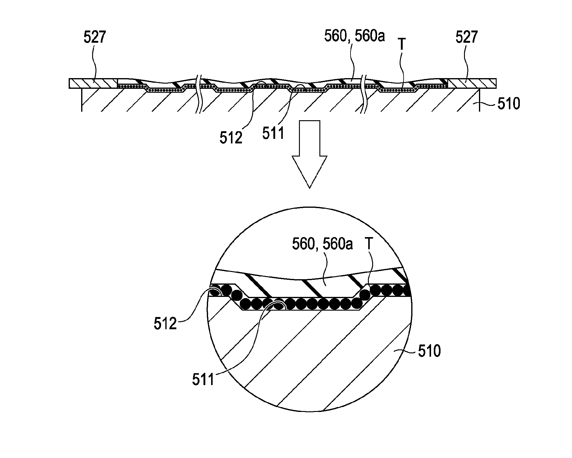
The nonuniformity of projections and depressions on the surface of the developing roller may locally cause poor electrification of the toner particles.
If the toner particles become stuck in the minute depressions, filming may be caused.
If the toner particles are not charged appropriately; the toner particles may leak out from the developing apparatus and be scattered in an image forming apparatus or fogging may occur on an image.
In recent years, there has been concern that dust is contained in a cooling airflow exhausted from electrophotographic image forming apparatuses to the outside, and the dust adversely affects the human body.
It is expected that one of the causes of dust generation is that an external additive having charge-leaking properties is liberated from the surface of toner and emitted to the outside of the image forming apparatus during its operation.
Therefore, there is also concern that part of the toner activated in a cloud form under the development electric field rides an airflow that flows in the image forming apparatus, whereby the toner becomes dust.
Secondly, a phenomenon of photo-conductor memory is caused.
However, a large amount of alumina fine particles remains left on the photo-conductor because the size is much smaller than that of the toner.

Method used


Image

  • Toner, method for forming image, and image forming apparatus
  • Toner, method for forming image, and image forming apparatus
  • Toner, method for forming image, and image forming apparatus

Examples


example 1

Preparation of Toner

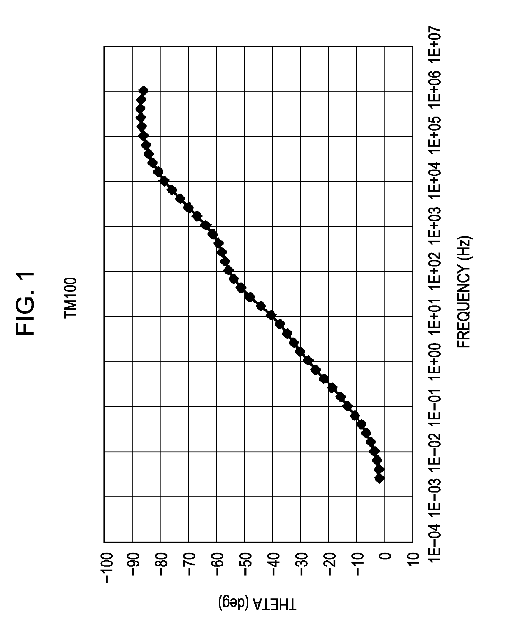
[0204]After 2 kg of toner base particles obtained by phase inversion emulsification were placed in a Henschel mixer (20 L), 2.0 g of alumina fine particles (TAIMICRON TM-100 (Al2O3) whose main phase is a θ-alumina phase and that has a primary particle size of 14 nm and a BET specific surface area of 132 m2 / g (available from TAIMEI CHEMICALS Co., Ltd.)) were placed in the Henschel mixer as an addition amount per 100 g of toner base particles (the same shall apply hereinafter) to perform processing at a peripheral speed of 40 m / s for 2 minutes.

[0205]Next, 2.0 g of hydrophobic monodispersed spherical large silica particles (KEP10S2 available from NIPPON SHOKUBAI Co., Ltd. having a primary particle size of 100 nm and processed with silicone oil) and 2.0 g of hydrophobic small silica particles (RX200 available from NIPPON AEROSIL Co., Ltd. having a primary particle size of 12 nm and is processed with hexamethyldisilazane (HMDS)) were placed in the Henschel mixer to pe...

example 2

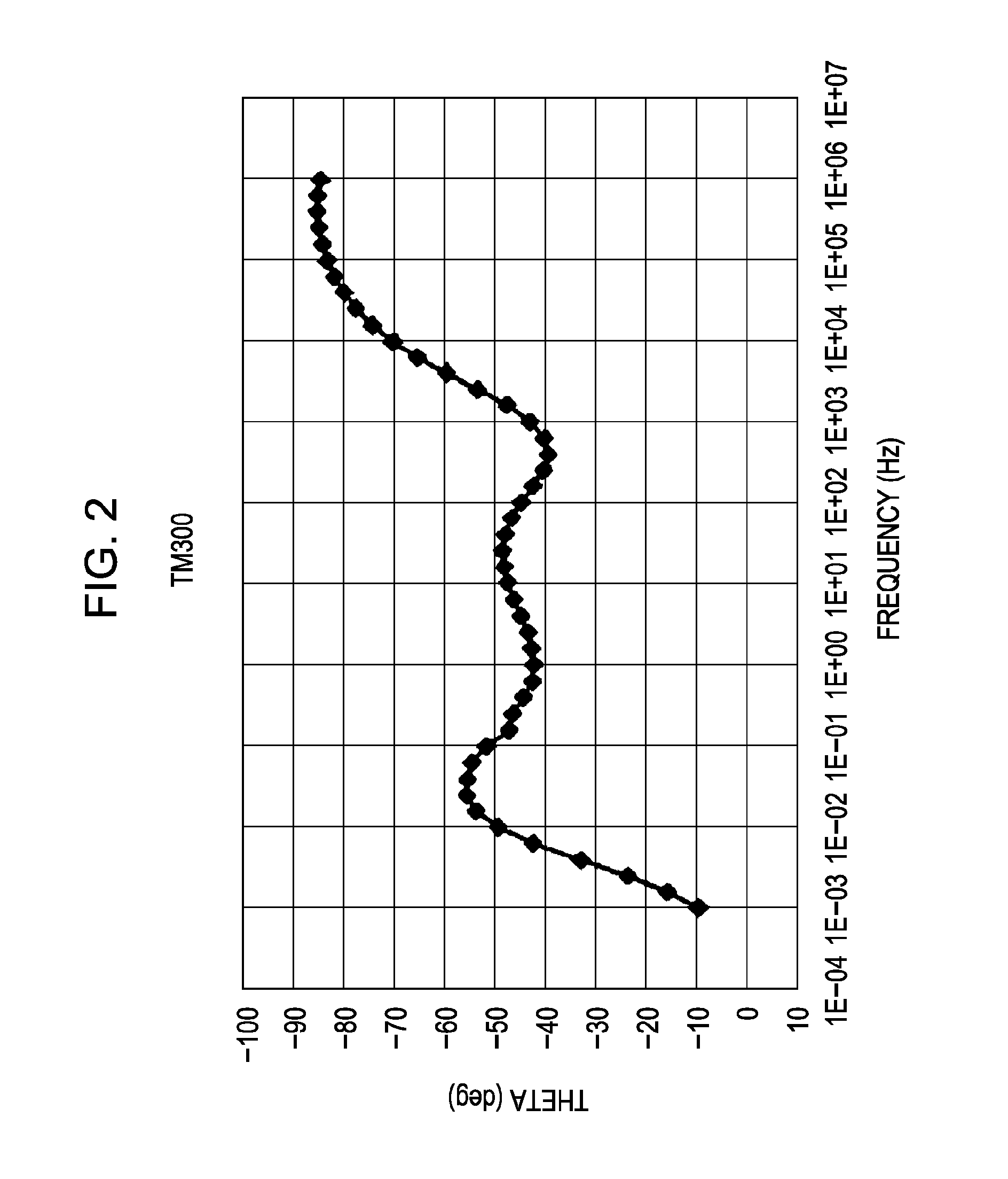
[0207]Toner of Example 2 was prepared in the same manner as in Example 1, except that the alumina fine particles were changed to 0.5 g of TAIMICRON TM-300 (Al2O3) whose main phase is a γ-alumina phase and that has a primary particle size of 7 nm and a BET specific surface area of 225 m2 / g (available from TAIMEI CHEMICALS Co., Ltd.).

example 3

[0208]Toner of Example 3 was prepared in the same manner as in Example 1, except that the alumina fine particles were changed to 2.0 g of Nano•Tek (Al2O3) having a primary particle size of 30 nm and a BET specific surface area of 49.3 m2 / g (available from C. I. Kasei Company, Limited).


PUM


Abstract

A toner includes toner base particles containing at least a binder resin, a coloring agent, and a release agent; and alumina fine particles whose phase angle (θ) is |80°| or less at an alternating current frequency of 1 to 10 kHz in an alternating current impedance method.

Description

BACKGROUND[0001]1. Technical Field[0002]The present invention relates to a toner, a method for forming an image, and an image forming apparatus.[0003]2. Related Art[0004]There have been image forming apparatuses that use a method including steps of rotatably mounting a photo-conductor such as a photosensitive drum or a photosensitive belt that is a latent image carrying unit onto a main body of an image forming apparatus, and during the image forming operation, forming an electrostatic latent image on a photosensitive layer of the photo-conductor, making the latent image visible in a contact or noncontact manner using toner, and directly transferring the visible image to a material to be transferred through corona transfer or using a transfer roller; or a method including steps of temporarily transferring the visible image to an intermediate transfer medium such as a transfer drum or a transfer belt and transferring the visible image to a material to be transferred again. In these i...

Claims


Application Information

Patent Timeline
Patent Type & Authority Applications(United States)
IPC IPC(8): G03G9/00G03G15/08
CPCG03G9/0819G03G15/0818G03G9/09708
Inventor OKADA, HIDEKIMORI, TOMOTAKAARUGA, TOMOHIRO
Owner SEIKO EPSON CORP
Learn More