Automatic bag breaking discharge device

A unloading device and bag breaking technology, which is applied in the directions of packaging, loading/unloading, transportation and packaging, etc., can solve the problems of incomplete bag breaking and unloading, large dust production, low efficiency, etc., and achieve good dust control effect, The effect of small dust production and high efficiency

Inactive Publication Date: 2015-07-08
WUHAN UNIV OF SCI & TECH
View PDF5 Cites 9 Cited by
  • Summary
  • Abstract
  • Description
  • Claims
  • Application Information

AI Technical Summary

Problems solved by technology

However, there are still problems such as large volume, large amount of dust, incomplete unloading of broken bags, and low efficiency. It has not been widely used in production practice.

Method used


Image

  • Automatic bag breaking discharge device
  • Automatic bag breaking discharge device
  • Automatic bag breaking discharge device

Examples


Embodiment 1

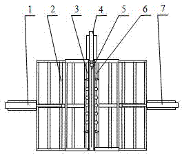
[0021] An automatic bag breaking and unloading device. Such as figure 1 As shown, the device includes a bag breaking cutter frame 2, a left bag breaking cutter 3, a bag cutting cutter 5 and a right bag breaking cutter 6.

[0022] Such as figure 1 As shown, a bag cutting tool 5 is installed in the middle position of the upper plane of the bag breaking tool frame 2 along the front and rear directions, and the left and right sides of the bag cutting tool 5 are correspondingly equipped with a left bag breaking tool 3 and a right bag breaking tool 6 , the left bag breaking tool 3 and the right bag breaking tool 6 are symmetrically arranged on the upper plane of the bag breaking tool frame 2. The working end of the piston rod of the bag cutting tool cylinder 4 is hinged with the bag cutting tool 5, the working end of the piston rod of the left bag breaking cylinder 1 is hinged with the left bag breaking tool 3, and the working end of the piston rod of the right bag breaking cy...

Embodiment 2

[0027] An automatic bag breaking and unloading device. Except following technical parameter, all the other are with embodiment 1:

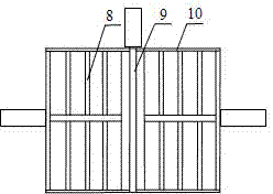
[0028] The sieve plate 8 is evenly provided with bar-shaped sieve holes, the width of the bar-shaped sieve holes is 20-30mm, and the sum of the hole areas of the bar-shaped sieve holes is 60-80% of the area of ​​the sieve plate 8;

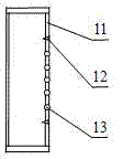
[0029] Steel nails 13 are evenly installed between the two triangular blades 12, and the number of steel nails 13 is 6 to 9;

[0030] The length of knife body is 80~85% of the cutter groove 9 lengths of bag breaking cutter frame 2.

[0031] This embodiment has the following positive effects:

[0032] 1) In this specific embodiment, a bag cutting tool 5 is installed in the middle position of the upper plane of the bag breaking tool frame 2 along the front and rear directions, and the left and right sides of the bag cutting tool 5 are correspondingly equipped with a left bag breaking tool 3 and a right side. The bag...


PUM


Abstract

The invention relates to an automatic bag breaking discharge device. According to the technical scheme, a bag cutting tool (5) is installed on the middle position of the upper plane of a bag breaking tool rack (2) in the front-back direction, a left bag breaking tool (3) and a right bag breaking tool (6) are correspondingly installed on the left side and the right side of the bag cutting tool (5), and the left bag breaking tool (3) and the right bag breaking tool (6) are symmetrically arranged on the upper plane of the bag breaking tool rack (2); the working end of a piston rod of a bag cutting tool air cylinder (4) is hinged to the bag cutting tool (5), the working end of a piston rod of a left bag breaking air cylinder (1) is hinged to the left bag breaking tool (3), and the working end of a piston rod of a right bag breaking air cylinder (7) is hinged to the right bag breaking tool (6); a cylinder body of the bag cutting tool air cylinder (4), a cylinder body of the left bag breaking air cylinder (1) and a cylinder body of the right bag breaking air cylinder (7) are fixed onto a middle support, a left support and a right support correspondingly. The automatic bag breaking discharge device has the advantages that the volume is small, the dust production volume is small, the efficiency is high, the labor intensity is small, the degree of automation is high, and the requirement of conducting continuous bag breaking and material discharging of powdery materials can be met.

Description

technical field [0001] The invention belongs to the technical field of powder material unloading. Specifically, it is an automatic bag breaking and unloading device. Background technique [0002] In the actual production process, there are usually many situations in which powdery materials are separated from their packaging bags. There are many ways of separation or unloading, including manual dumping, drum unloading and vibration unloading. The artificial dumping method not only produces a large amount of dust, but also causes workers to be directly exposed to high-concentration dust, which threatens the physical and mental health of the workers, and also causes low production efficiency and affects labor efficiency; Waste, and the vibration unloading method produces a large amount of dust, which increases the difficulty of subsequent dust removal. [0003] How to reduce the workload of workers, prevent dust pollution, protect the physical and mental health of workers and...

Claims


Application Information

Patent Timeline
Patent Type & Authority Applications(China)
IPC IPC(8): B65B69/00B65G47/16B65G69/18
CPCB65B69/0033B65G47/16B65G69/18
Inventor 陈旺生谢小蕾宋孝红
Owner WUHAN UNIV OF SCI & TECH
Why Eureka
Try Eureka