Image Forming Apparatus

Active Publication Date: 2014-09-11
BROTHER KOGYO KK
View PDF5 Cites 4 Cited by
  • Summary
  • Abstract
  • Description
  • Claims
  • Application Information

AI Technical Summary

Benefits of technology

[0006]With the manual-feeder tray occupying in the upper range with respect to the feeder tray, a volume of a space inside the chassis, which may be accessed by a user through the opening, may be reduced. Therefore, it may be difficult for the user to insert his/her hand through the opening toward the rear side when, for example, a jammed recording sheet needs to be removed, or other maintenance works are required.
[0007]Further, with the manual-feeder tray in the inclined posture,

Problems solved by technology

Therefore, it may be difficult for the user to insert his/her hand through the opening toward the rear side when, for example, a jammed recording sheet needs to be removed, or other maintenance works are require

Method used


Image

  • Image Forming Apparatus
  • Image Forming Apparatus
  • Image Forming Apparatus

Examples


Embodiment Construction

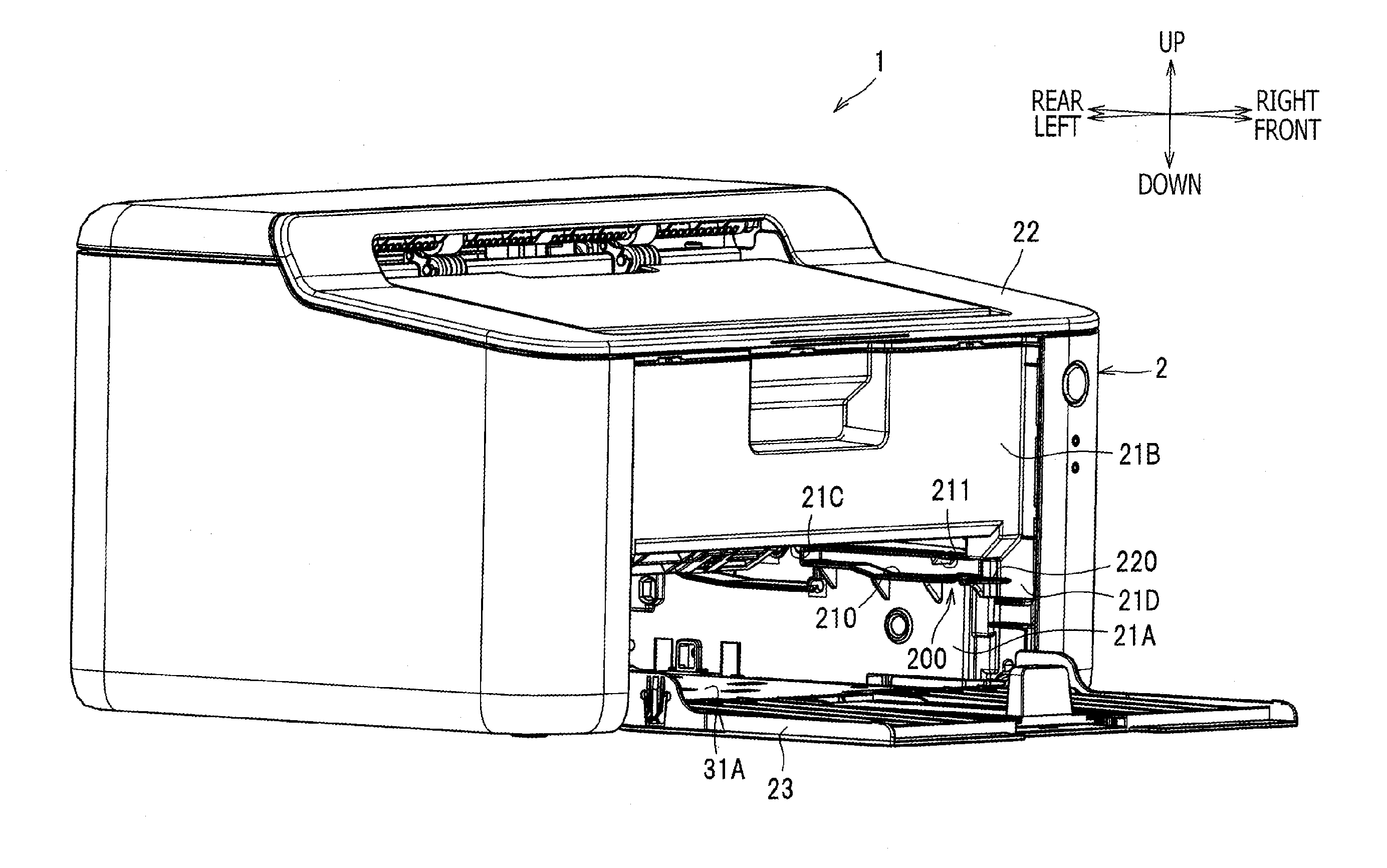
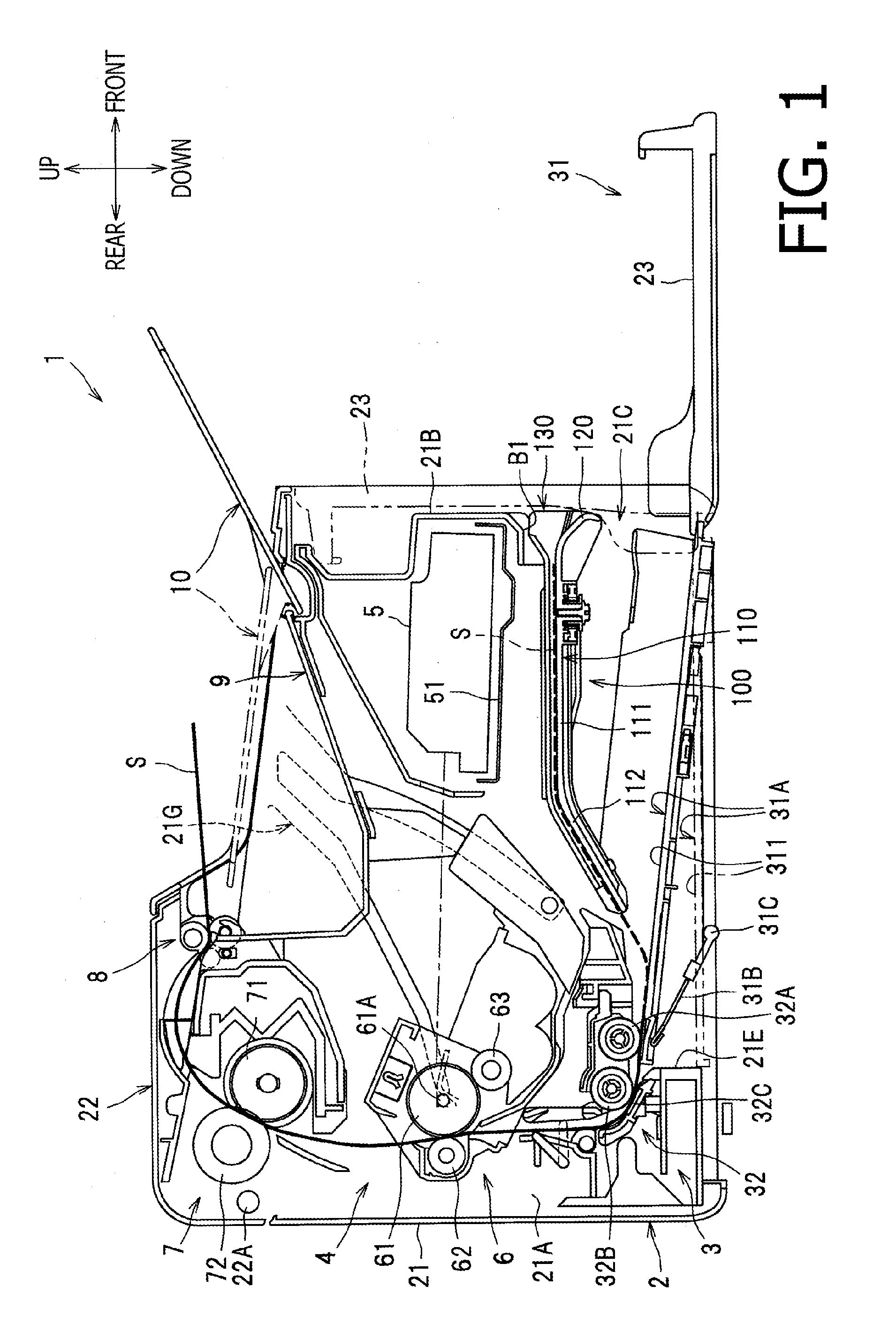
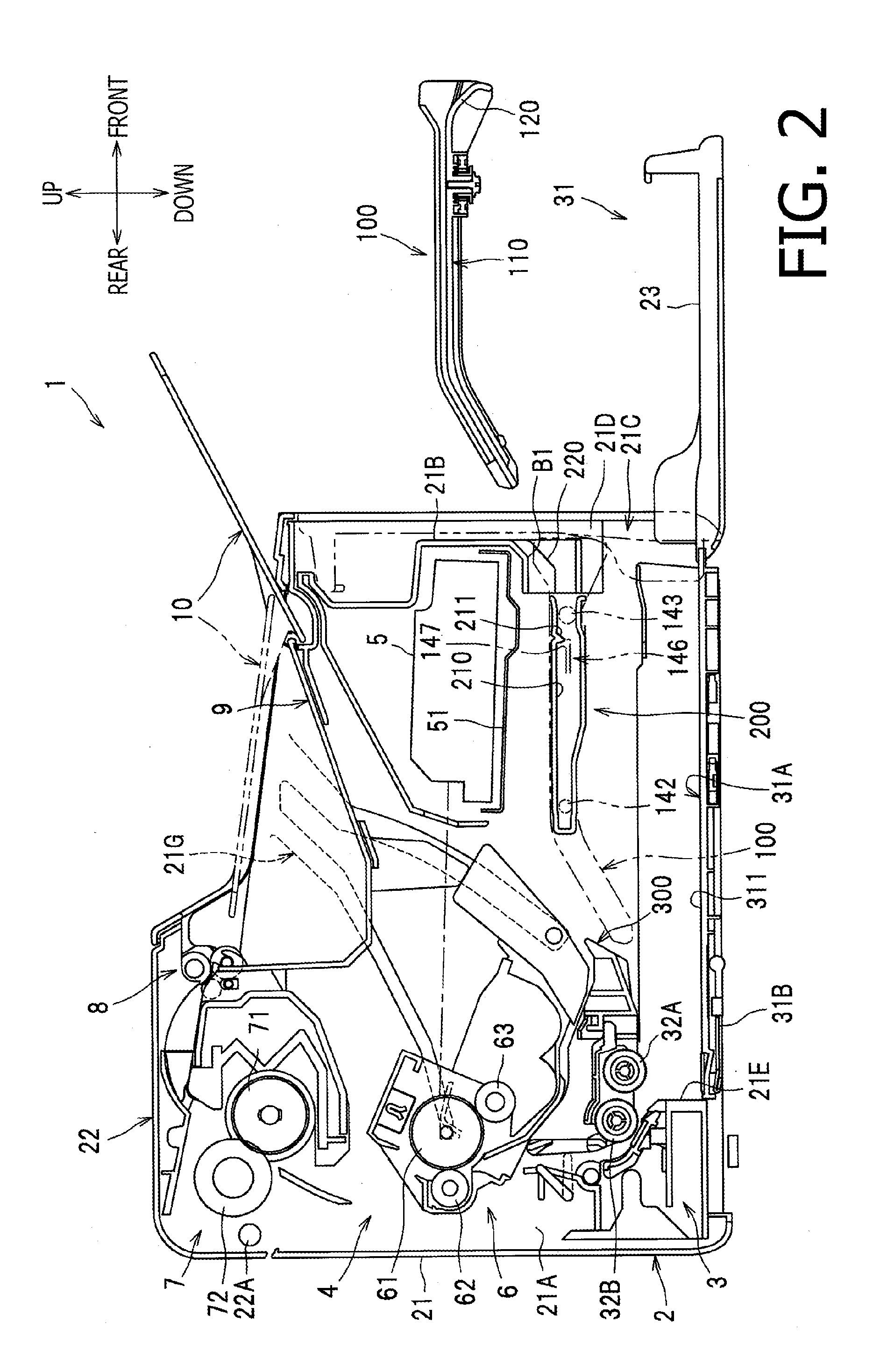
[0021]Hereinafter, an embodiment according to an aspect of the present invention will be described with reference to the accompanying drawings. In the following description, first, an overall configuration of a laser printer 1 being an image forming apparatus will be described, and second, detailed configuration of specific parts in the laser printer 1 will be described.

[0022]In the present embodiment, directions concerning the laser printer 1 will be referred to in accordance with orientation indicated by arrows in each drawing. Therefore, for example, a viewer's right-hand side appearing in FIG. 1 is referred to as a front side of the laser printer 1, and a left-hand side in FIG. 1 opposite from the front side is referred to as a rear side. A side which corresponds to the viewer's nearer side is referred to as left, and an opposite side from the left, which corresponds to the viewer's farther side is referred to as right. The up-down direction in FIG. 1 corresponds to a vertical d...


PUM


Abstract

An image forming apparatus, including a chassis with an opening formed on one side thereof; a first placement section, on which a sheet inserted through the opening is placeable; a cover configured to be openable to expose and closable to cover the opening and configured to form, when in a position to expose the opening, an outer part of the first placement section outside the chassis; and a second placement section arranged in an upper position with respect to the first placement section, and on which a sheet inserted through the opening is placeable, is provided. The second placement section is detachably attached to the chassis through the opening.

Description

CROSS REFERENCE TO RELATED APPLICATION[0001]This application claims priority from Japanese Patent Application Nos. 2013-045177, 2013-045180, and 2013-045185, filed on Mar. 7, 2013, the entire subject matters of which are incorporated herein by reference.BACKGROUND[0002]1. Technical Field[0003]An aspect of the present invention relates to an image forming apparatus having a manual sheet feeder tray.[0004]2. Related Art[0005]Conventionally, an image forming apparatus with a chassis, in which a recording sheet to be fed to an image forming unit can be inserted through an opening formed on one side (e.g., a front side) of the chassis, is known. The image forming apparatus may have a feeder tray, on which the recording sheets inserted through the opening are placed, and a manual-feeder tray, on which the recording sheets manually inserted through the opening are placed. The recording sheets to be placed on the feeder tray may be inserted through a lower part of the opening, and the recor...

Claims


Application Information

Patent Timeline
IPC IPC(8): B65H1/04B65H9/00B65H3/06
CPCB65H1/04B65H9/00B65H3/0684B65H3/0615B65H3/0607B65H2402/46B65H2403/411B65H2405/1111B65H2405/11162B65H2405/12B65H2405/31B65H2405/324B65H2405/332B65H2407/21B65H2511/12B65H2511/22B65H2220/01B65H2220/04B65H2402/412B65H2402/441B65H2402/442
Inventor MINOSHIMA, SAYAUEYAMA, JUNKI
Owner BROTHER KOGYO KK
Why Eureka
Try Eureka