Induction machine

a technology of induction machine and main magnetic flux, which is applied in the direction of dynamo-electric machines, synchronous motors, electrical apparatus, etc., can solve the problems of reducing electric power loss, reducing power factor improvement, and not achieving the reduction of electric power loss, so as to improve power factor, reduce leakage flux of main magnetic flux, and increase efficiency

Inactive Publication Date: 2014-09-11
HITACHI LTD
View PDF10 Cites 30 Cited by
  • Summary
  • Abstract
  • Description
  • Claims
  • Application Information

AI Technical Summary

Benefits of technology

[0036]According to the present invention, it is possible to provide an induction machine that improves the power factor and in...

Problems solved by technology

It is known that the induction machine generates a harmonic magnetic flux due to slot permeance pulsation or a magnetomotive force distribution and that a loss is thereby increased.
However, i...

Method used


Image

  • Induction machine
  • Induction machine
  • Induction machine

Examples


first embodiment

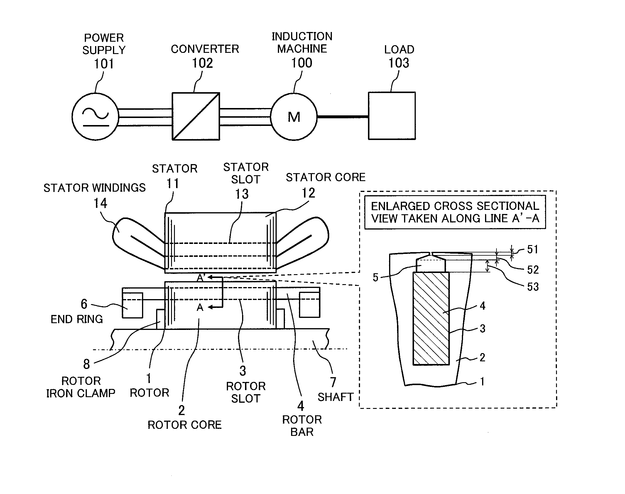
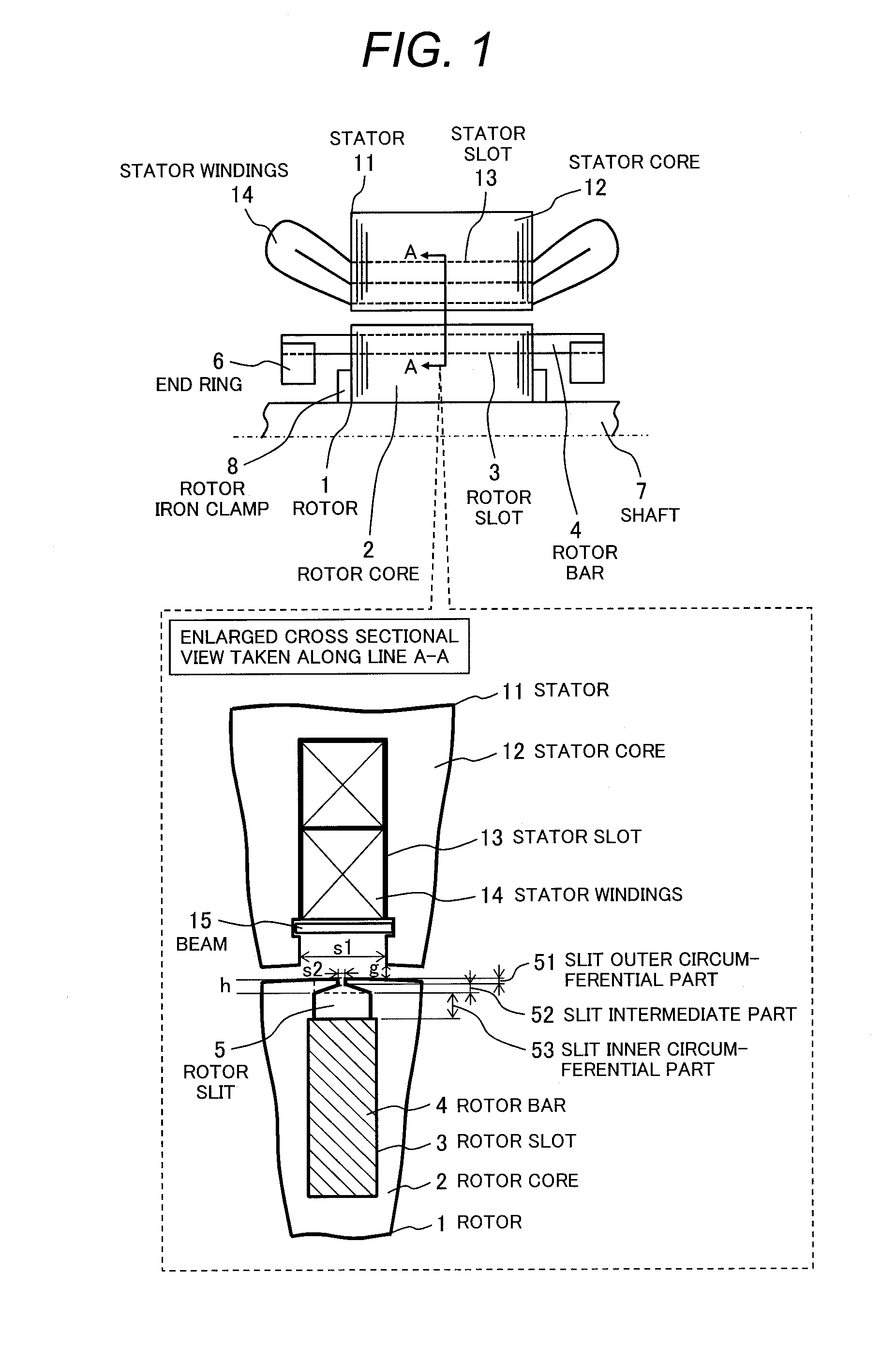
[0058]FIG. 1 is schematic drawings showing a longitudinal sectional view in the axial direction of a squirrel-cage induction machine, an upper half portion, according to a first embodiment of the present invention and an enlarged cross sectional view thereof taken along line A-A. As indicated in the schematic drawings of FIG. 1, the squirrel-cage induction machine includes a shaft 7, a rotor 1 secured to the shaft 7, a stator 11 that faces the rotor 1 with a gap left therebetween, and other elements.

[0059]Furthermore, the stator 11 has a plurality of stator slots 13, which are placed in its circumferential direction at a predetermined interval, in an inner circumferential part, each rotor slot 13 being formed continuously in its axial direction. The stator 11 also has a stator core 12, which is formed by laminating a plurality of thin steel sheets such as electromagnetic steel sheets in its axial direction, and stator windings 14 loaded in the plurality of stator slots 13.

[0060]The ...

second embodiment

[0093]In a second embodiment of the present invention, dimensions of individual parts of the rotor slit 5 described in the first embodiment will be defined to obtain preferable advantageous effects. FIG. 7 is a schematic drawing showing an enlarged cross sectional view around a rotor slot of a squirrel-cage induction machine according to a second embodiment of the present invention. In FIG. 7, the dimensions of individual parts of the rotor slit 5 are indicated as symbols.

[0094]As shown in FIG. 7, an inclination angle formed by the slit intermediate part 52 with respect to the circumferential direction is denoted θ, the width of the slit inner circumferential part 53 at an innermost circumferential position in the circumferential direction is denoted W, the height of the slit inner circumferential part 53 in its radial direction is denoted β, the outer circumferential width of the rotor bar 4 in the circumferential direction is denoted Wb, and the width of a step, which is a differe...

third embodiment

[0109]There will be described regarding a third embodiment of the present invention. FIG. 11 is a schematic drawing showing an enlarged cross sectional view around a rotor slot of an induction machine according to a third embodiment. As shown in FIG. 11, an induction machine of the third embodiment differs from that of the first embodiment in which the slit opening (the rotor slit width S2) of the slit outer circumferential part 51 is shifted toward the delayed side in the rotational direction of the rotor 1, and in which the delayed sides of the slit outer circumferential part 51, slit intermediate part 52, and slit inner circumferential part 53 are aligned on a straight line.

[0110]When, in the third embodiment, a preferable range is obtained from the efficiency map of FIG. 8, an inclination angle θ2 formed by the slit intermediate part 52 in the circumferential direction on the advanced side in the rotational direction of the rotor 1 is represented as in the following Equation (3)...


PUM


Abstract

There is provided an induction machine having a squirrel-cage rotor, the rotor including: a rotor core; a plurality of rotor slots formed on the rotor core and aligned circumferentially at a predetermined interval; a plurality of rotor bars inserted into one of the plurality of rotor slots; and a plurality of rotor slits formed adjacent to the plurality of rotor slots on an outer circumferential side of the rotor core. The each rotor slit is formed as a hollow such that a cross sectional shape thereof is distinguished into three parts of a slit outer circumferential part, a slit intermediate part, and a slit inner circumferential part. A circumferential width of the each rotor slit on an innermost circumferential side is larger than that on an outermost circumferential side. A circumferential width of the slit intermediate part increases from an outer circumferential side toward an inner circumferential side.

Description

CLAIM OF PRIORITY[0001]The present application claims priority from Japanese patent application serial no. 2013-043724 filed on Mar. 6, 2013, the content of which is hereby incorporated by reference into this application.BACKGROUND OF THE INVENTION[0002]1. Field of the Invention[0003]The present invention relates to an induction machine such as an induction motor or an induction generator, and particularly to an induction machine having a structure that can reduce a copper loss generated in a rotor conductor.[0004]2. Description of Related Art[0005]Induction machines are being used in many industrial fields. In these years, as a social tendency, there is a need for an induction machine that satisfies a demand for energy conservation and resource conservation. To respond to this requirement, many improved technologies have been proposed to increase the efficiency of the induction machines.[0006]It is known that the induction machine generates a harmonic magnetic flux due to slot perm...

Claims


Application Information

Patent Timeline
IPC IPC(8): H02K17/16
CPCH02K17/165H02K2213/03
Inventor KUNIHIRO, NAOKINISHIHAMA, KAZUOIIZUKA, MOTONOBUSUGIMOTO, KENICHISAWAHATA, MASANORIKOMURA, AKIYOSHI
Owner HITACHI LTD
Why Eureka
Try Eureka