Cutter cartridge device, adjusting jig and cutting apparatus

a cartridge device and adjusting jig technology, applied in the direction of metal-working machine components, instruments, manufacturing tools, etc., can solve the problems of poor cutting, user difficulty in visually adjusting the blade portion projection amount properly, and small blade portion projection amount, etc., to achieve the effect of easy adjustment of the blade portion projection amoun

Active Publication Date: 2014-09-18
BROTHER KOGYO KK
View PDF17 Cites 12 Cited by
  • Summary
  • Abstract
  • Description
  • Claims
  • Application Information

AI Technical Summary

Benefits of technology

[0008]Therefore, an object of the disclosure is to provide a cutter cartridge device, an adjusting jig and a cutting apparatus, all of which can easily adjust a projection amount of the blade portion of the cutter to a proper amount.

Problems solved by technology

When the amount of projection of the blade portion is smaller than a thickness of the object, a part of the object cannot be cut out from the object with the result that poor cutting occurs.
However, since the blade portion is small and paper and cloth serving as the object to be cut have respective small thicknesses, a projection amount of the blade portion is obviously small.
Accordingly, the user has a difficulty in visually adjusting a projection amount of the blade portion properly.

Method used


Image

  • Cutter cartridge device, adjusting jig and cutting apparatus
  • Cutter cartridge device, adjusting jig and cutting apparatus
  • Cutter cartridge device, adjusting jig and cutting apparatus

Examples


Embodiment Construction

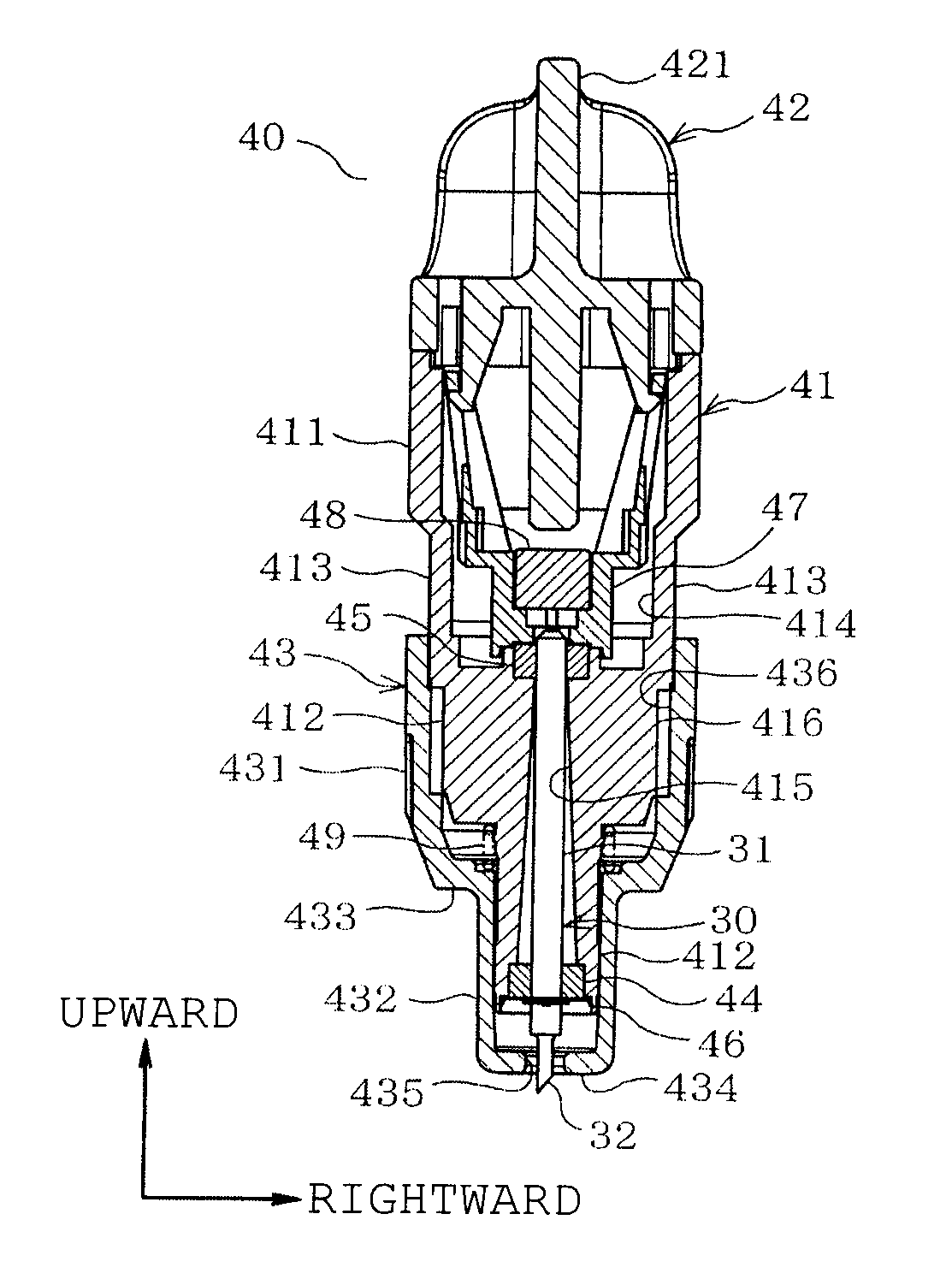
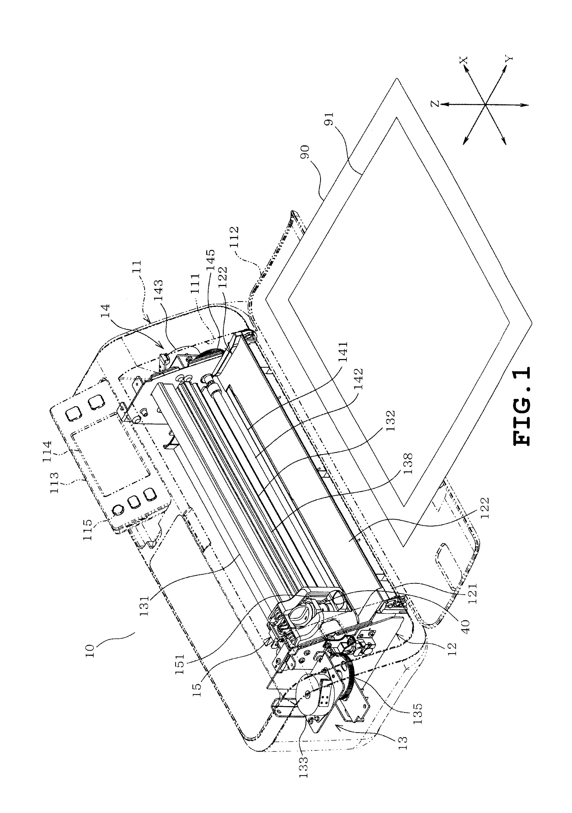
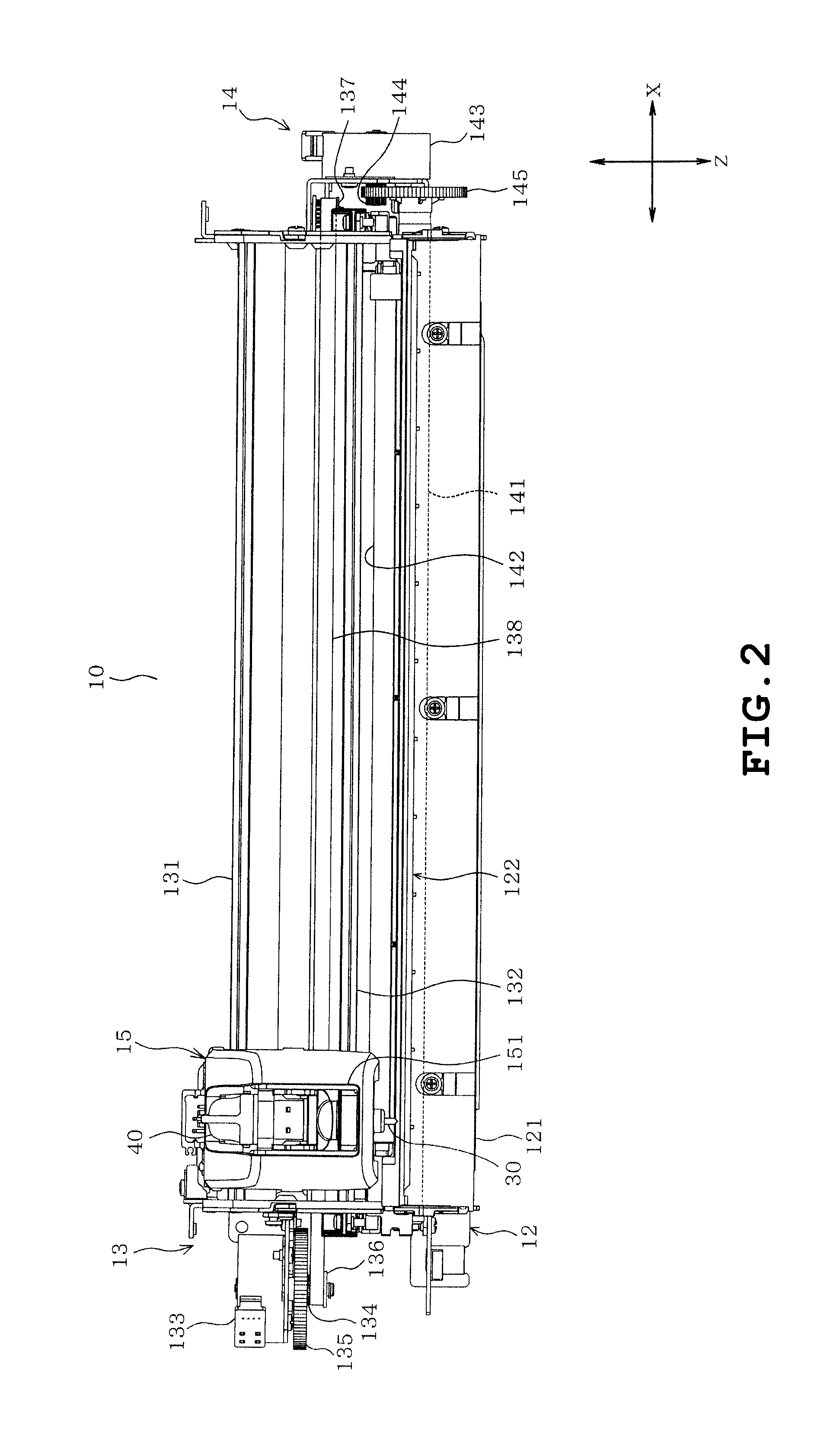
[0024]A cutter cartridge device, an adjusting jig and a cutting apparatus according to one example will be described with reference to the accompanying drawings. Referring to FIGS. 1 and 2, the cutting apparatus 10 is shown which cuts an object 91 held by a holding member 90 into a desired shape. The holding member 90 is a flat plate made of a resin and having an adhesive layer (not shown) on a surface thereof. The holding member 90 holds the object 91 such as cloth or paper affixed to the adhesive layer. The cutting apparatus 10 includes a body cover 11, a cutting apparatus body 12, an X-axis moving mechanism 13, a Y-axis moving mechanism 14 and a carriage 15, as shown in FIGS. 1 and 2. The cutting apparatus 10 also includes a cartridge 40 provided with a cutter 30 as shown in FIG. 2. The cartridge 40 is detachably attached to the carriage 15 as shown in FIG. 2.

[0025]The body cover 11 is formed into the shape of a rectangular box as a whole and covers the body 12, the X-axis moving...


PUM

PropertyMeasurementUnit
depthaaaaaaaaaa
depthaaaaaaaaaa
thicknessaaaaaaaaaa

Abstract

A cutter cartridge device includes a cartridge having a cutter including a blade portion, the blade portion being configured so that an amount of projection thereof projecting from the cartridge is changeable, an adjusting jig including an attachment portion configured so that the cartridge is detachably attachable and a holder portion configured to hold a sheet-shaped cut object from both thicknesswise ends with respect to the cut object, the holder portion having a spacing which is changed in conjunction with a change in the projection amount of the blade portion of the cartridge attached to the attachment portion.

Description

CROSS-REFERENCE TO RELATED APPLICATIONS[0001]This application is based upon and claims the benefit or priority from the prior Japanese Patent Application No. 2013-053190 filed on Mar. 15, 2013, the entire contents of which are incorporated herein by reference.BACKGROUND[0002]1. Technical Field[0003]The present disclosure relates to a cutter cartridge device including a cartridge and an adjusting jig, the adjusting jig and a cutting apparatus including the cutter cartridge device or a cutting apparatus including the cartridge and the adjusting jig.[0004]2. Related Art[0005]A cutting apparatus, such as so-called cutting plotter, has been conventionally known which cuts an object to be cut, such as paper or cloth, into a desired configuration. A cutter holder (corresponding to a cartridge) is detachably attached to this type of cutting plotter. In this case, the cutter holder includes a cylindrical holder portion holding a cutter therein and a cap which is threadingly engaged with the ...

Claims


Application Information

Patent Timeline
Patent Type & Authority Applications(United States)
IPC IPC(8): B26D7/26B26F1/38
CPCB26F1/3813B26D7/2628B26D7/2614B26D2007/2678Y10T83/9488
Inventor NIIZEKI, TOMOYASU
Owner BROTHER KOGYO KK
Why Eureka
Try Eureka