Saw blade with feed limiter

a technology of blades and limiters, which is applied in the field of saw blades, can solve the problems of affecting affecting the so as to achieve the effect of improving the overall cutting efficiency of the blad

Active Publication Date: 2014-09-18
BLACK & DECKER INC
View PDF9 Cites 10 Cited by
  • Summary
  • Abstract
  • Description
  • Claims
  • Application Information

AI Technical Summary

Benefits of technology

[0008]It is an object of the present invention to overcome one or more of the above-described drawbacks and / or disadvantages of the prior art to provide a chip limiter that both protects against over-feeding, while also aiding in the overall cutting efficiency of the blade.
[0013]In some embodiments, the chip limiter is configured to substantially prevent more than about 30% of an object, such as a pipe or a metal fastener, e.g., a nail, screw, having a diameter of at least about 40% of the pitch from contacting the respective trailing tooth.
[0018]In some embodiments, the secondary cutting tooth is configured to substantially prevent more than about 30% of an object, such as, for example, a pipe or metal fastener, e.g., a nail or screw, having a diameter of at least about 40% of the pitch from contacting the respective trailing primary cutting tooth.

Problems solved by technology

However, such blades are susceptible to failure upon encountering an occasional hard material, such as a, nail or screw (typically having a diameter of at least about 40% of the tooth pitch) or staple when the hard material falls too far into a tooth gullet beyond the end of a tooth tip.
This type of failure can also occur with the cutting of pipes or materials where the cut cross-section changes depending on the blade's location within the cut e.g. on a pipe where the cut cross-section is wide at the top and then is drastically reduced as the saw approaches the cross-section that is perpendicular to the cutting direction.
This “over-feeding” of the hard material, forces the trailing tooth to cut a large portion of the hard material, thus forcing a bigger chip load than the trailing tooth can handle.
Under these circumstances, the tooth may not withstand the resultant shearing force, resulting in fracture.
Additionally, saw stalling may be induced, leading to injury.
Similarly, specialty reciprocating saw blades, such as diamond or carbide tipped blades, are very effective when used for their intended purposes, but perform very poorly if misapplied.
The material at the tip of these blades possesses a higher hardness than a typical bi-metal blade, and consequently is also more brittle.
This renders such blades susceptible to catastrophic failure when they come in contact with a hard material, such as a pipe, nail, screw or staple, due to their brittleness.
In such instance, the tip may fracture, crumble, or rip from the weld or solder with the blade body.
However, such shallow clearance angles sacrifice cutting efficiency and the life of the blade in exchange for some potential prevention of tooth fracture.
Further, the extension of the clearance surface to form the humps can reduce gullet volume, reducing chip removal capacity / efficiency, or require a larger tooth pitch, which reduces cutting capacity / efficiency or requires modification of the teeth to make up the loss, which can further exacerbate the problem of breakage when encountering hard materials.
However, none of these configurations prevent the underlying problem of over-feeding.

Method used


Image

  • Saw blade with feed limiter
  • Saw blade with feed limiter
  • Saw blade with feed limiter

Examples


Embodiment Construction

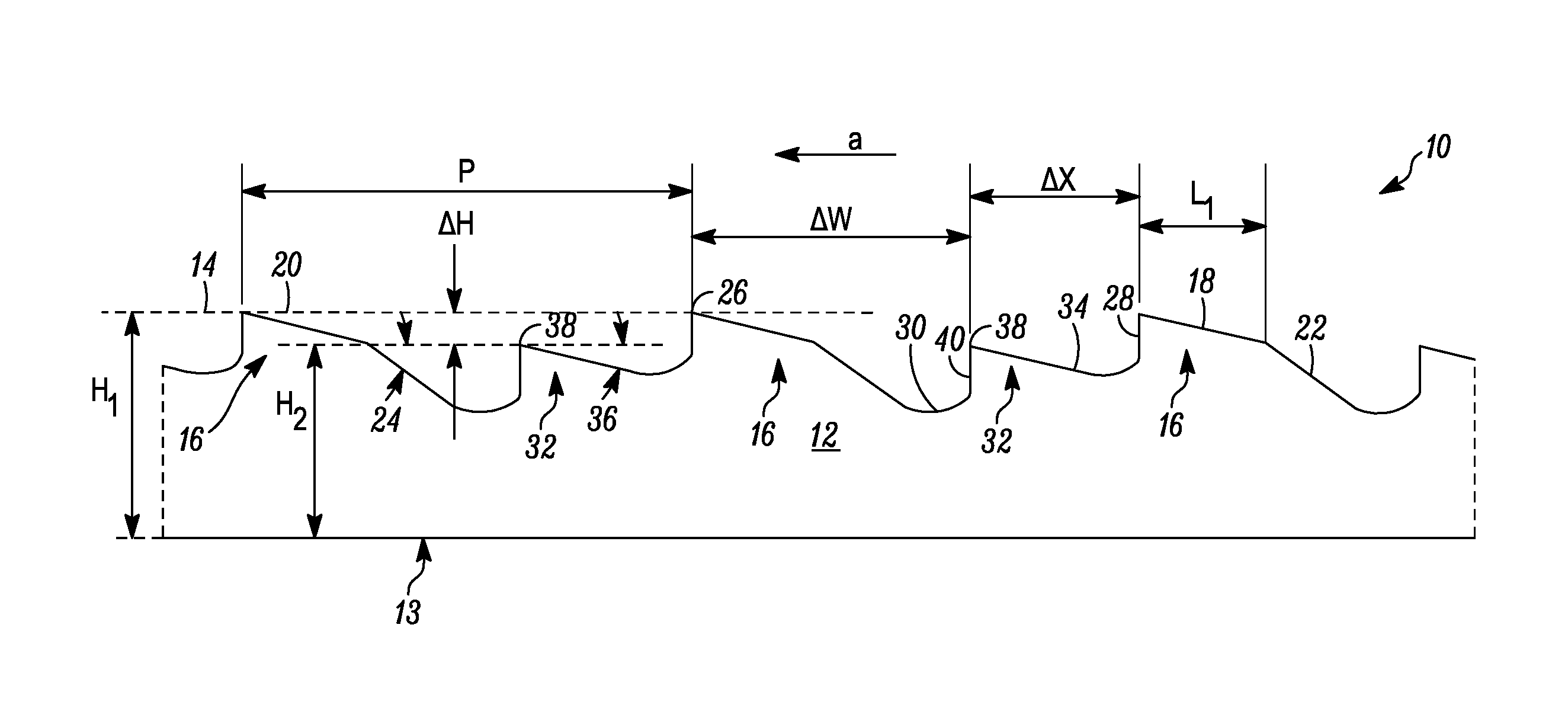
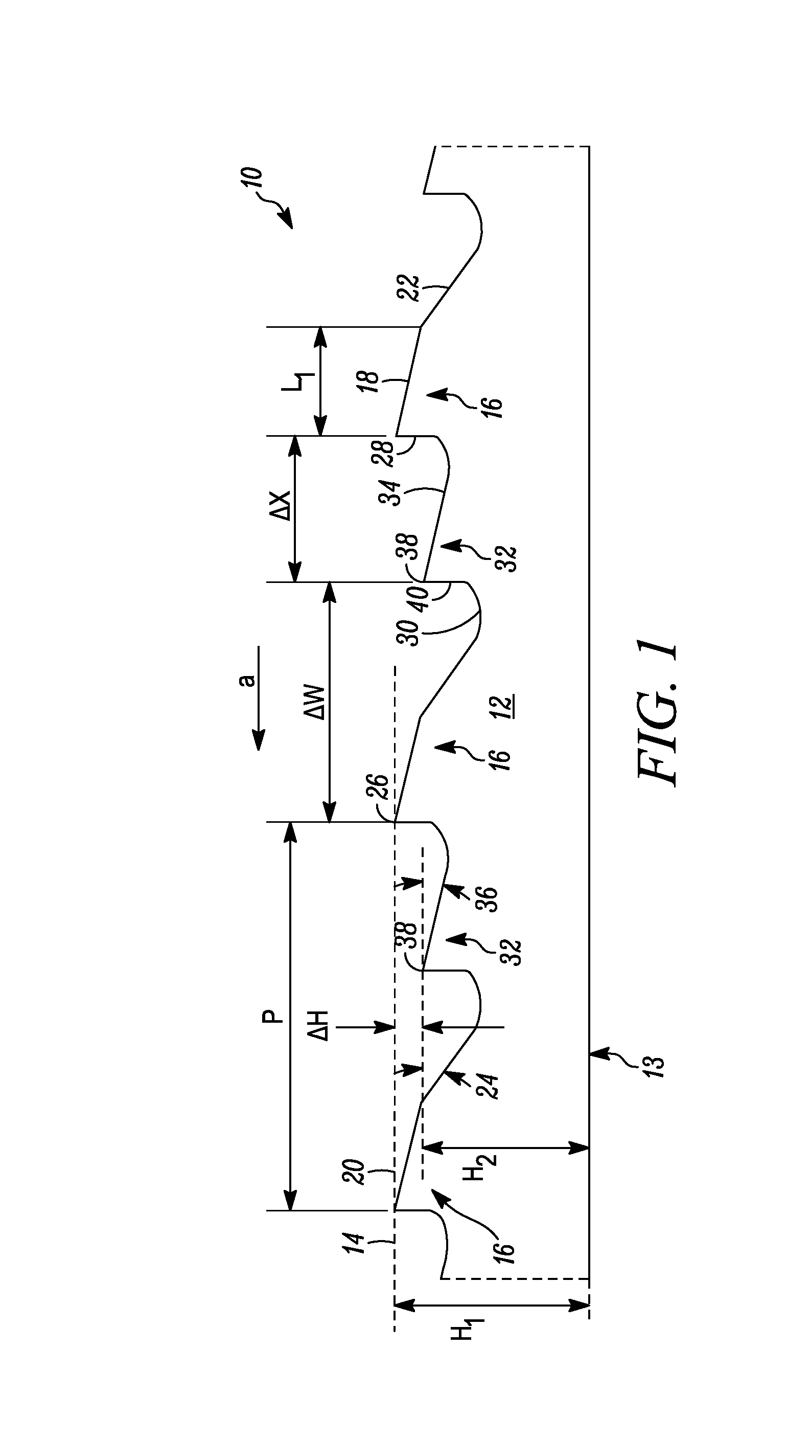
[0034]In FIG. 1, a first embodiment of a reciprocating saw blade is indicated generally by the reference numeral 10. The saw blade 10 is usable in a reciprocating saw. The saw blade 10 comprises a generally elongated blade body 12 having a back edge 13 and a cutting edge 14 extending along a cutting portion of the blade body 12 on an opposite side of the blade body 12 from the back edge 13 and defined by a plurality of cutting teeth 16, in this embodiment a repeating pattern of teeth. Each tooth 16 includes a primary clearance surface 18 defining a primary clearance angle 20 between the primary clearance surface 18 and a plane parallel to the cutting edge 14, a secondary clearance surface 22 defining a secondary clearance angle 24 between the secondary clearance surface and a plane parallel to the cutting edge 14, a tip 26, a rake face 28 located on the opposite side of the tip 26 relative to the primary clearance surface 18, and a gullet 30. In other exemplary embodiments, such as ...


PUM

PropertyMeasurementUnit
clearance angleaaaaaaaaaa
relief angleaaaaaaaaaa
clearance anglesaaaaaaaaaa

Abstract

A saw blade comprising cutting teeth, having at least one of chip-limiters protruding from the teeth or secondary teeth in the gullets of the cutting teeth configured to mitigate the blade from over-feeding. The chip limiters and / or secondary teeth provide that only a limited portion of an object that the saw blade encounters during cutting falls below the cutting tips of the cutting teeth. The chip limiters and / or secondary teeth also assist the cutting teeth in cutting.

Description

FIELD OF THE INVENTION[0001]The present invention relates to saw blades, and more particularly, to saw blades with chip limiting features to prevent over-feeding.BACKGROUND OF THE INVENTION[0002]A reciprocating saw machine is a hand-held power saw that includes a chuck for releasably engaging the saw blade and driving the saw blade in a reciprocating motion through a work piece. The reciprocating motion can be an orbital cutting action, a straight or linear cutting action, or an angled cutting action. The length or stroke of the reciprocating motion is typically about 1½ inches or less. Reciprocating saws are sometimes referred to as “recip” saws, jig saws, and power hack saws, and the term reciprocating saw is used herein without limitation to mean reciprocating saw machines, jigsaw machines, and portable power hack machines. Reciprocating saws typically are driven by electric motors (e.g., cord or cordless saws) or are pneumatically driven. Well-known reciprocating saws are sold u...

Claims


Application Information

Patent Timeline
Patent Type & Authority Applications(United States)
IPC IPC(8): B23D61/12
CPCB23D61/121Y10T83/9319Y10T83/9348
Inventor ELLISTON, ASIFKORB, WILLIAM B.HAMPTON, STEPHEN A.FOSBERG, DOUGLAS K.KALOMERIS, CHARLES E.
Owner BLACK & DECKER INC
Why Eureka
Try Eureka