
Cutting Device for a Sewing Machine

a cutting device and sewing machine technology, applied in the field of sewing machines, to achieve the effect of reducing relative manufacturing and assembly costs, and simplifying the structure of the upper-blade positioning devi

Active Publication Date: 2014-09-18
TSENG HSIEN CHANG
View PDF3 Cites 13 Cited by
  • Summary
  • Abstract
  • Description
  • Claims
  • Application Information

AI Technical Summary

Benefits of technology

The present invention provides a cutting device for a sewing machine that enhances the stability of movement of the upper blade with an upper-blade drive member that cooperates with a guide member fixed on the base. The lower-blade positioning device has an adjustment member that can be rotated by a rotary button for easier and more efficient adjustment. The upper-blade positioning device is simplified with an integrally designed and provided upper-blade drive member for mounting of relative parts of the upper-blade positioning device, reducing manufacturing and assembling cost.

Problems solved by technology

However, the applicant of the present invention is not satisfied with the improvement made in the Taiwan Patent serial No. 90224753 and has made further improvement to the sewing machine of Patent No. 6892658.

Method used


Image

  • Cutting Device for a Sewing Machine
  • Cutting Device for a Sewing Machine
  • Cutting Device for a Sewing Machine

Examples


Embodiment Construction

[0019]The present invention will be clearer from the following description when viewed together with the accompanying drawings, which show, for purpose of illustrations only, the preferred embodiment in accordance with the present invention.

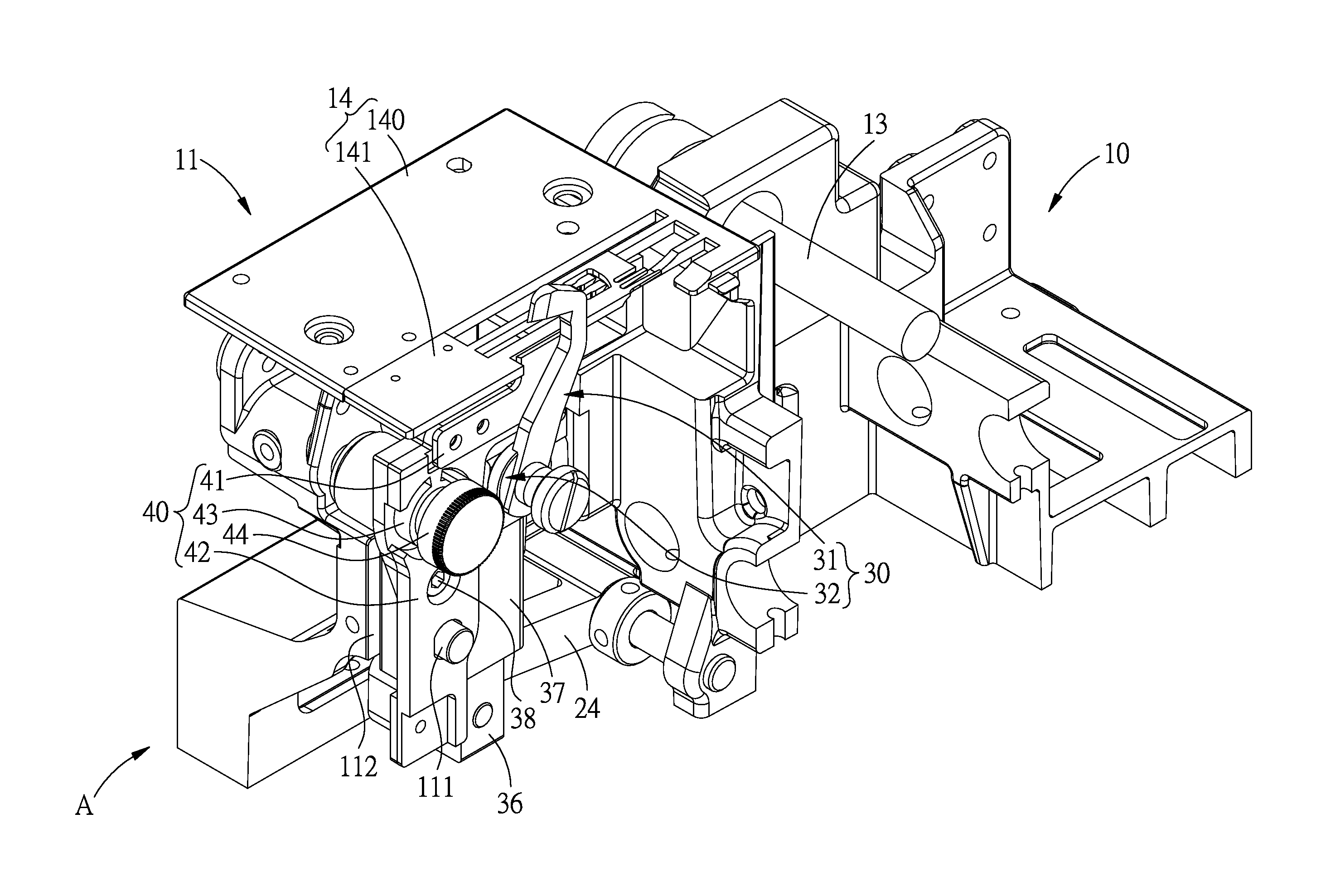
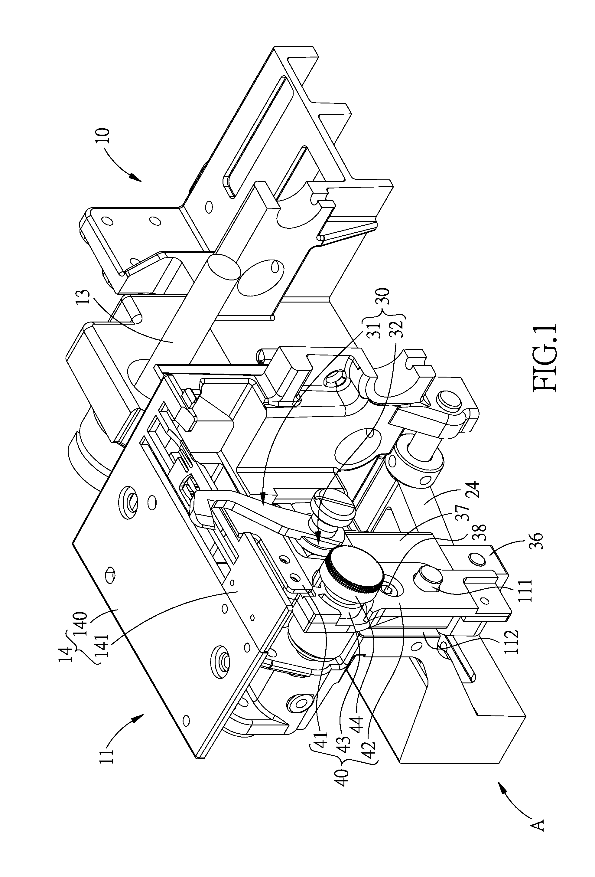
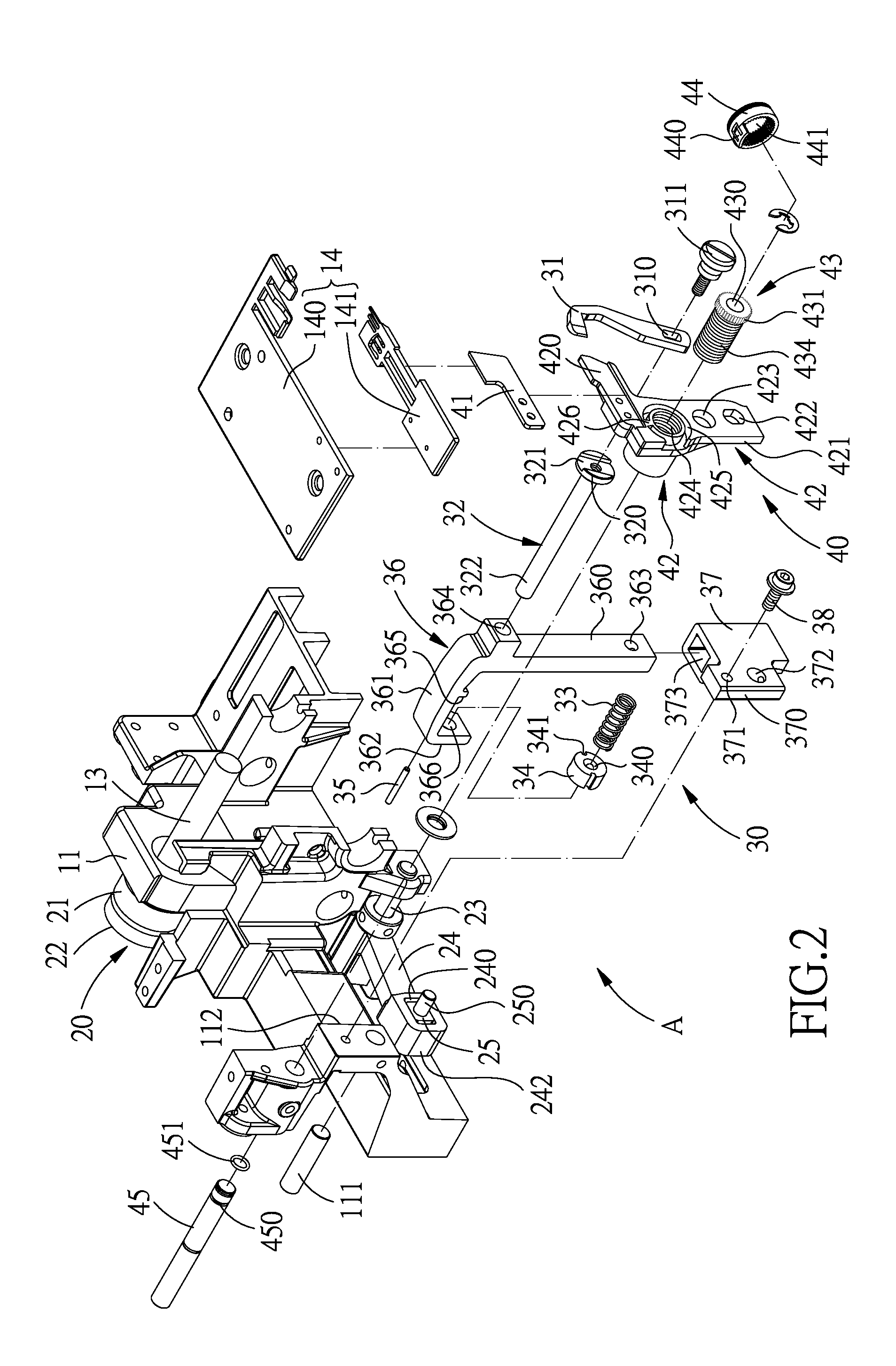
[0020]Referring to FIGS. 1-3, a cutting device A for a sewing machine 10 in accordance with the present invention is disposed in a base 11 of the sewing machine 10. A cantilever extends from the base 11, and a driven shaft 13 is disposed inside the base 11 to simultaneously drive the drive parts which are disposed inside the base 11 and the cantilever. At a free end of the cantilever is fixed a needle (not shown) which repeatedly moves and down, the cutting device A is located under the needle, and above the needle is a needle plate 14 which includes a first part 140 and a second part 141. The cutting device A includes an upper blade 31 and a lower blade 41 and devices for moving and positioning the upper and lower blades 31, 41. In the base 11 i...


PUM


Abstract

A cutting device for a sewing machine includes an upper-blade positioning device and a lower-blade positioning device. The upper-blade positioning device includes an upper blade upper blade fixed at a head portion of the upper-blade holder, and a spring and a restricting member sleeved on a body portion of the upper-blade holder. A restricting pin is engaged between an upper-blade drive member and the restricting member. A guide member includes a guide hole for insertion of a rod portion of the upper-blade drive member and is fixed to the base. The upper-blade drive member is inserted through a guide member of the base and moved by a connecting rod. The lower-blade positioning device includes a lower-blade holder, an adjustment member. A lower-blade shaft has one end fixed to the base and another end extended out of the base, rotating the adjustment member can adjust the position of the lower-blade holder.

Description

BACKGROUND OF THE INVENTION[0001]1. Field of the Invention[0002]The present invention relates to a sewing machine, and more particularly to a cutting device for a sewing machine.[0003]2. Description of the Prior Art[0004]The applicant's former invention called “cutting structure for a sewing machine” has been patented in Taiwan with the patent serial No. 90224753 and another invention called “sewing machine” has also been patented in USA with the patent No. 6892658. Both inventions are invented based on the working principle of the four-bar linkage mechanism to make the upper blade move stably, and allow the lower blade to be adjusted in position with respect to the needle plate.[0005]However, the applicant of the present invention is not satisfied with the improvement made in the Taiwan Patent serial No. 90224753 and has made further improvement to the sewing machine of Patent No. 6892658.[0006]The present invention has arisen to mitigate and / or obviate the afore-described disadvan...

Claims


Application Information

Patent Timeline
Patent Type & Authority Applications(United States)
IPC IPC(8): D05B37/06D05B65/02
CPCD05B65/02D05B37/063D05B37/06D05B65/00
Inventor TSENG, HSIEN-CHANG
Owner TSENG HSIEN CHANG
Learn More