Laboratory testing-based valve prognostics

a technology of laboratory testing and valve prognosis, applied in the direction of testing/monitoring control system, electric programme control, instruments, etc., can solve the problem of component performance degrading over tim

Active Publication Date: 2014-09-18
FISHER CONTROLS INT LLC
View PDF12 Cites 35 Cited by
  • Summary
  • Abstract
  • Description
  • Claims
  • Application Information

AI Technical Summary

Problems solved by technology

That component performance degrades over time as a result of the changing values of that operating parameter.

Method used


Image

  • Laboratory testing-based valve prognostics
  • Laboratory testing-based valve prognostics
  • Laboratory testing-based valve prognostics

Examples


Embodiment Construction

[0016]Although the following text sets forth a detailed description of numerous different embodiments, it should be understood that the legal scope of the description is defined by the words of the claims set forth at the end of this patent. The detailed description is to be construed as exemplary only and does not describe every possible embodiment since describing every possible embodiment would be impractical, if not impossible. Numerous alternative embodiments could be implemented, using either current technology or technology developed after the filing date of this patent, which would still fall within the scope of the claims.

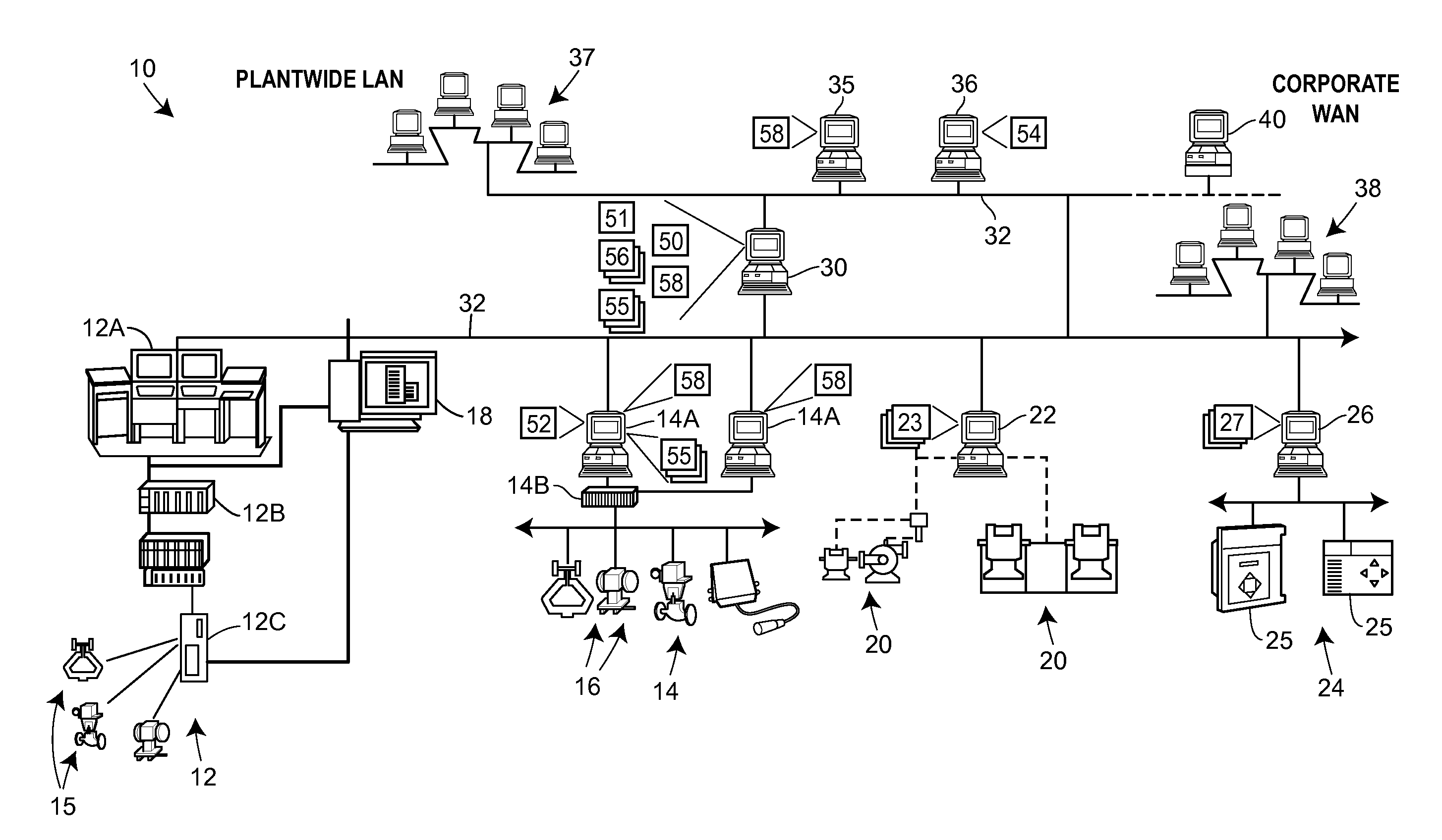
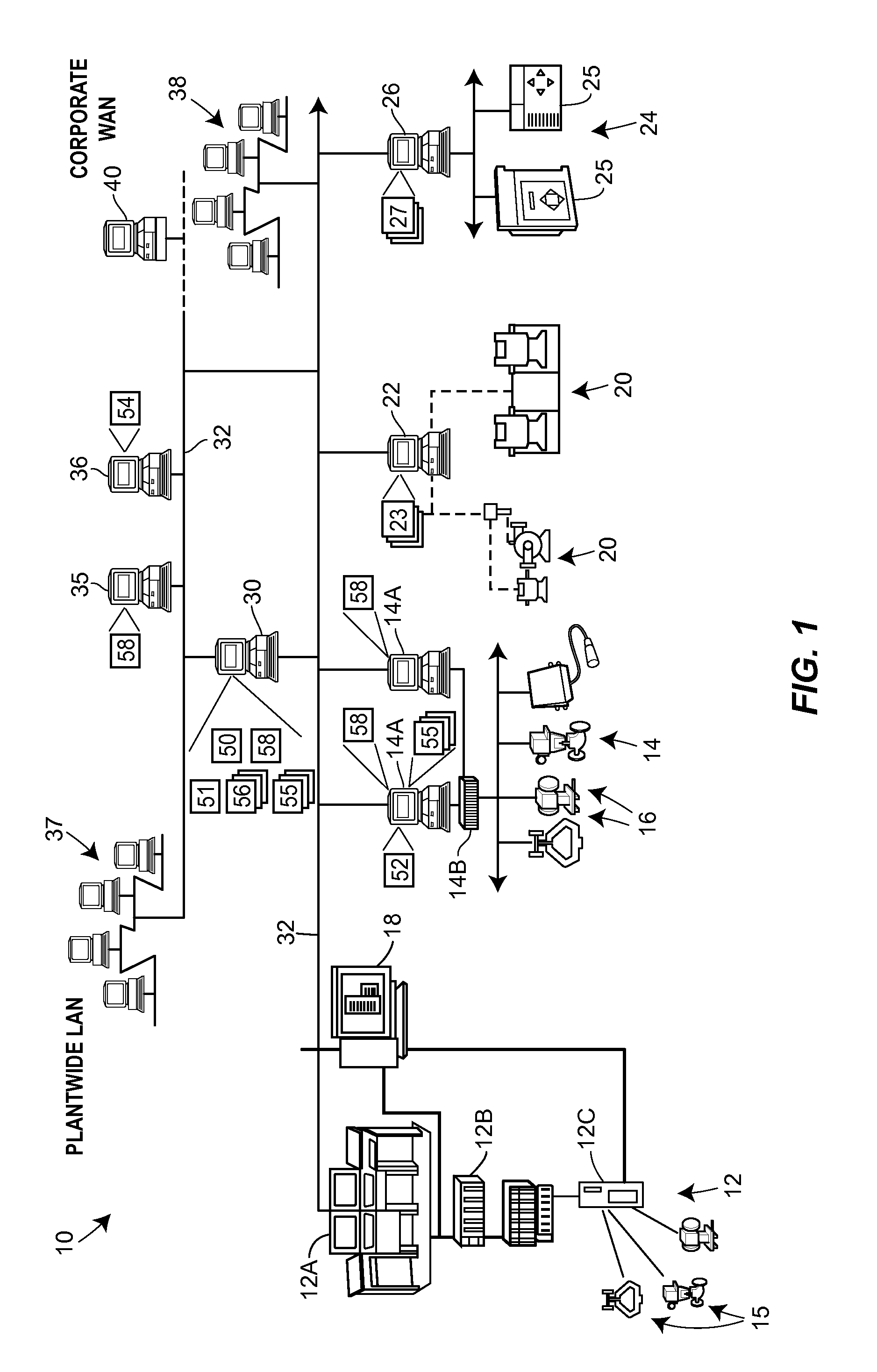
[0017]Referring now to FIG. 1, a process plant 10 includes a number of business and other computer systems interconnected with a number of control and maintenance systems by one or more communication networks.

[0018]The process control system 12 and 14 may be, for example, DeltaVTM controllers sold by Fisher-Rosemount Systems, Inc. of Austin, Tex. or any ot...


PUM


Abstract

The claimed method and system develops a useful lifetime profile for a component of a process control device, such as a valve, and uses that lifetime profile to determine a projected remaining lifetime for the device component in operation. The lifetime profile is developed from using real world operational data of similar process control devices, used under substantially the same operating conditions as to be experienced during operation. Profiles may be developed for numerous device components, from which a projected lifetime profile for the entire process control device is developed. Based on the projected remaining lifetime, notification warnings may be sent to remote computers and maintenance scheduling may be automatically achieved.

Description

RELATED APPLICATIONS[0001]This application claims the benefit of priority of U.S. Provisional Patent Application 61 / 785,073, filed Mar. 14, 2013, entitled “Laboratory Testing-Based Valve Prognostics,” which application is hereby incorporated herein by reference in its entirety and for all purposes.FIELD OF TECHNOLOGY[0002]The present disclosure relates to process control devices within process plants and, more specifically, to techniques for performing lifetime prognostics on the process control devices.BACKGROUND[0003]Existing process control systems may perform periodic diagnostics on process control devices, such as valves, to determine the operability and performance of such devices. Determining the operability of a process control device may permit better scheduling of maintenance of the process control device, thereby decreasing failure occurrences and down time. This may result in increased efficiency, safety, and revenue. The process control systems may use various sensors a...

Claims


Application Information

Patent Timeline
Patent Type & Authority Applications(United States)
IPC IPC(8): G01M99/00F16K37/00
CPCG01M99/00F16K37/0075G05B23/0283G06Q10/20Y10T137/8158Y02P90/80G05B19/418
Inventor GRABAU, TED DENNISANDERSON, SHAWN W.
Owner FISHER CONTROLS INT LLC
Why Eureka
Try Eureka