Rack assembly

a rack and assembly technology, applied in the field of rack assembly, can solve the problems of difficult to easily install racks in the office, difficult to carry heavy loads, difficult to disassemble racks, etc., and achieve the effect of reducing the amount of transportation space, easy disassembly and assembly, and convenient disassembly

Inactive Publication Date: 2014-09-18
TSENG CHING CHAO
View PDF27 Cites 7 Cited by
  • Summary
  • Abstract
  • Description
  • Claims
  • Application Information

AI Technical Summary

Benefits of technology

[0008]The present invention relates to a rack assembly and comprises at least four columns, a top frame module and a bottom frame module. The top frame module comprises a top frame, a top connection unit connected to the top frame, and at least four top fixing slots. The top connection unit comprises multiple top connection parts. The at least four top fixing slots are formed by connections of the top frame and the top connection parts. The bottom frame module comprises a bottom frame, a bottom connection unit connected to the bottom frame, and at least four bottom fixing slots. The bottom connection unit has multiple bottom connection parts. The at least four bottom fixing slots are formed by connections of the bottom frame and the bottom connection parts. The at least four columns are connected between the top and bottom frame modules by locking units. The rack assembly can be easily disassembled for reducing the room required in transportation, and the rack assembly can be easily assembled in offices.

Problems solved by technology

However, significant space is required when transporting the racks to the users' offices.
When the doors of the offices are small, the racks are difficult to be easily installed in the offices.
The conventional assembled racks use adapting connectors at the corners of the racks, however, stress are concentrated at these adapting connectors at the corners so that the connection can be easily damaged and cannot used for heavy load.

Method used


Image

  • Rack assembly
  • Rack assembly
  • Rack assembly

Examples


Embodiment Construction

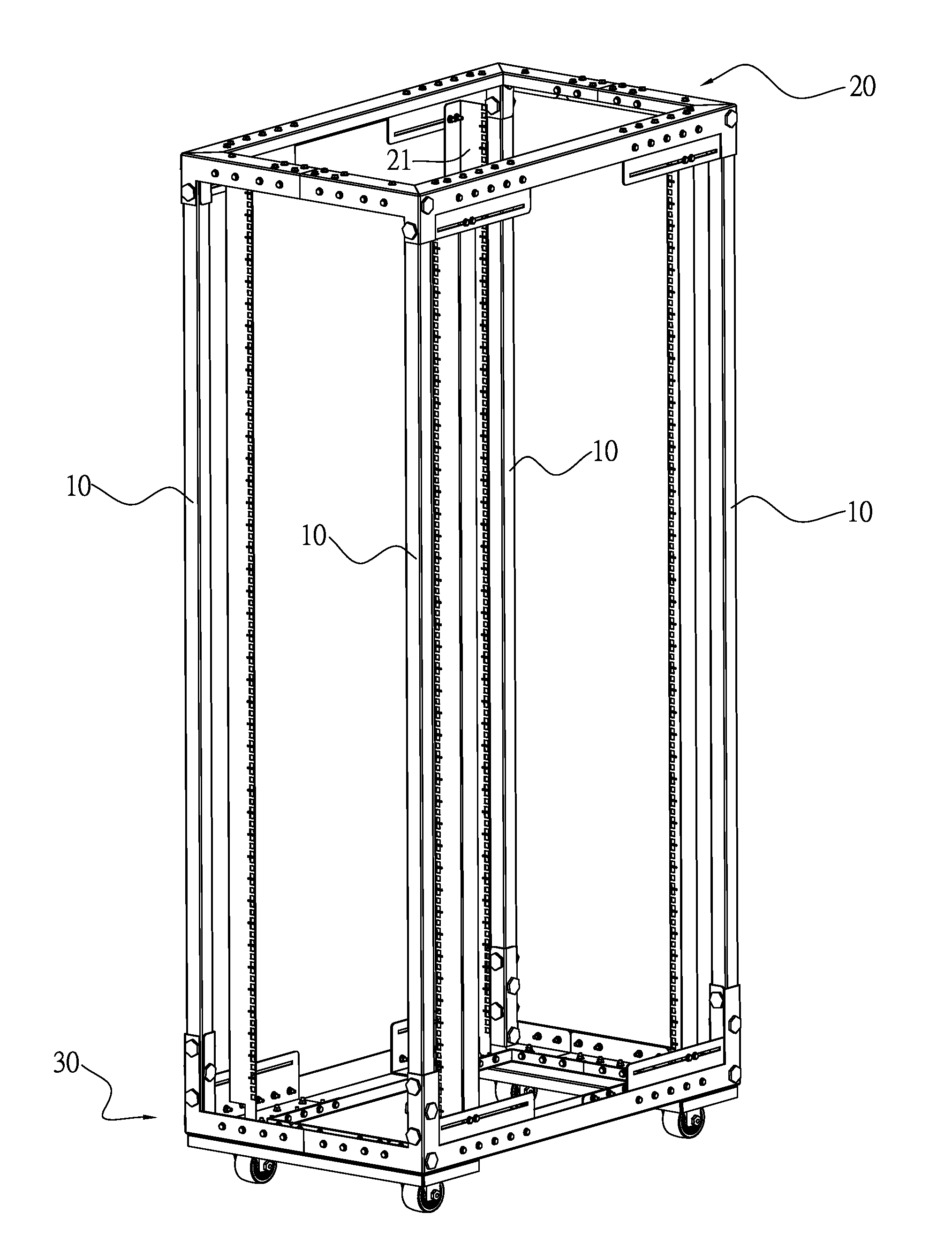
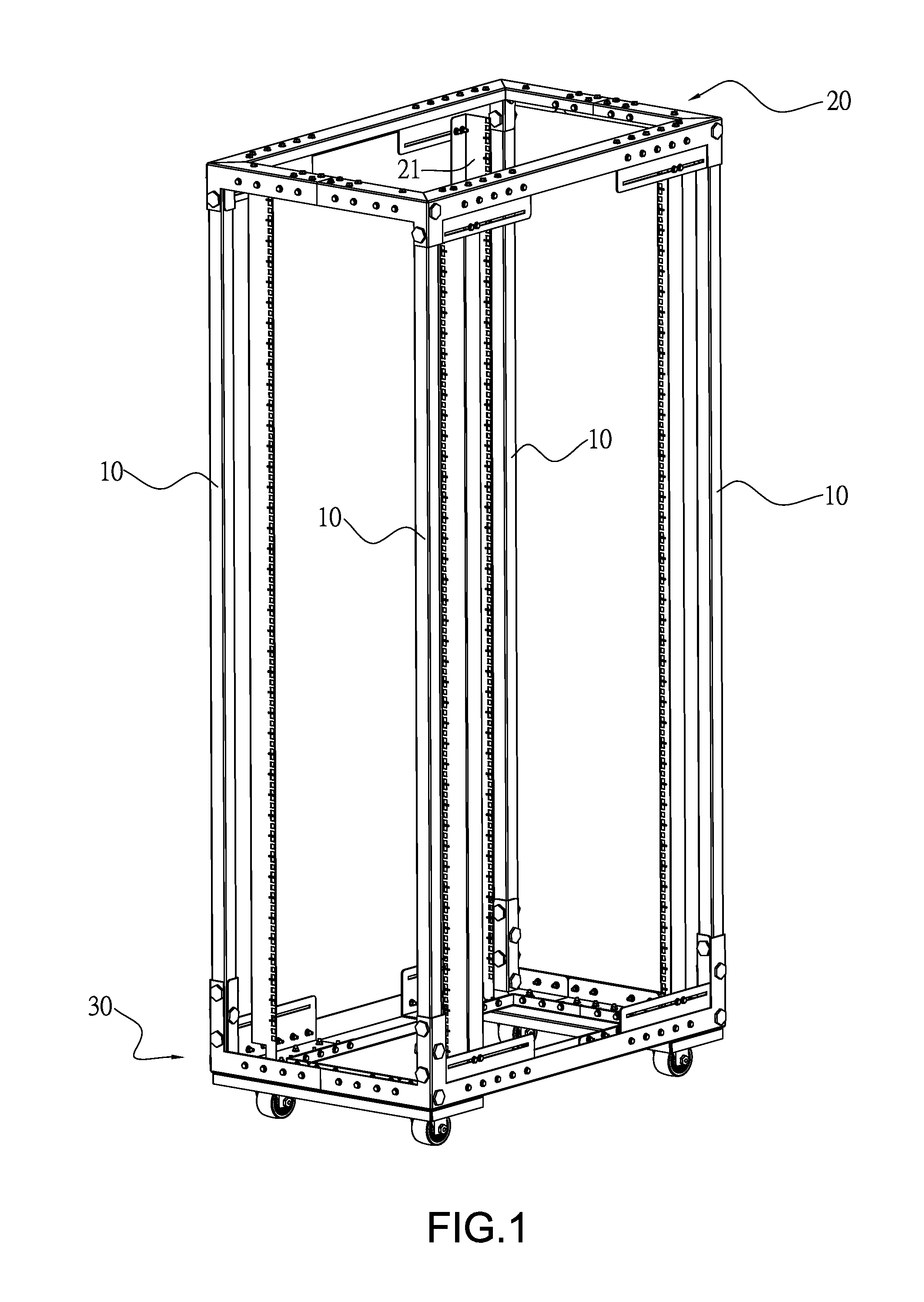
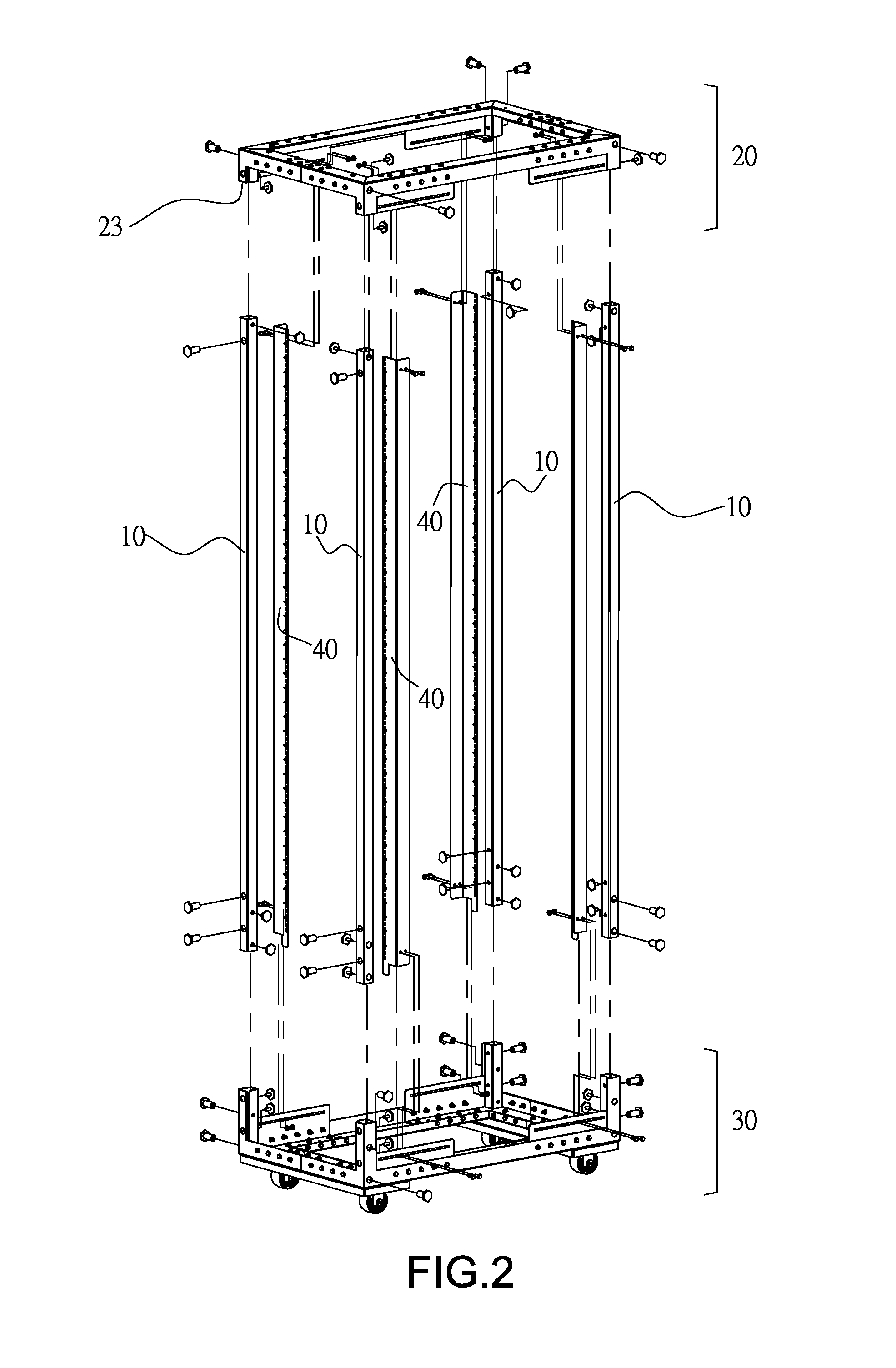
[0030]Referring to FIGS. 1 and 2, the rack assembly of the present invention comprises four columns 10, a top frame module 20 and a bottom frame module 30, so as to reduce the room required when in transportation and the ability for management of load is also increased.

[0031]As shown in FIGS. 2 to 5, the top frame module 20 comprises a top frame 21, a top connection unit 22 and at least four top fixing slots 23. The top connection unit 22 has multiple top connection parts 221 which are connected to the inside of the top frame 21. The at least four top fixing slots 23 each are formed by connections of the top frame 21 and the top connection parts 221, and the four columns 10 have their respective four first ends inserted into the at least four top fixing slots 23. Each of the four columns 10 and each of the at least four top fixing slots 23 are secured by at least one top locking unit T1 so as to secure the relative position between the column 10 and the top fixing slot 23. The top f...


PUM


Abstract

A rack assembly includes at least four columns, a top frame module and a bottom frame module. The at least four columns are connected between the top and bottom frame modules. The rack assembly can be easily disassembled for reducing the room required in transportation, and the rack assembly can be easily assembled in offices.

Description

BACKGROUND OF THE INVENTION[0001](1) Field of the Invention[0002]The present invention relates to a rack assembly, and more particularly, to a rack assembly that is composed of various parts and has strength for heavy load.[0003](2) Description of the Prior Art[0004]The conventional racks are used for managing servos and computers so as to store the data and be connected with computers and electronic equipments of different departments needs.[0005]The conventional racks are manufactured by the manufacturing factories and each rack is manufactured by assembling and welding processes. The finished racks are then sent to the users' offices. However, significant space is required when transporting the racks to the users' offices. When the doors of the offices are small, the racks are difficult to be easily installed in the offices.[0006]The conventional assembled racks use adapting connectors at the corners of the racks, however, stress are concentrated at these adapting connectors at t...

Claims


Application Information

Patent Timeline
Patent Type & Authority Applications(United States)
IPC IPC(8): A47F5/01
CPCH05K7/1488
Inventor TSENG, CHING-CHAO
Owner TSENG CHING CHAO
Why Eureka
Try Eureka