Welding system having an auxiliary charger

a technology of auxiliary charger and welding system, which is applied in the field of hybrid engine driven welding systems having auxiliary chargers, can solve the problems of inefficiency in the activation of the engine-generator to meet such small load demands

Active Publication Date: 2014-09-18
ILLINOIS TOOL WORKS INC
View PDF12 Cites 21 Cited by
  • Summary
  • Abstract
  • Description
  • Claims
  • Application Information

AI Technical Summary

Benefits of technology

[0005]In another embodiment, a method includes maintaining a float charge of a battery of a hybrid welding power supply unit when the power output produced by the hybrid welding power supply unit is reduced from a base load.

Problems solved by technology

However, activation of the engine-generator to meet such small load demands is often inefficient.

Method used


Image

  • Welding system having an auxiliary charger
  • Welding system having an auxiliary charger
  • Welding system having an auxiliary charger

Examples


Embodiment Construction

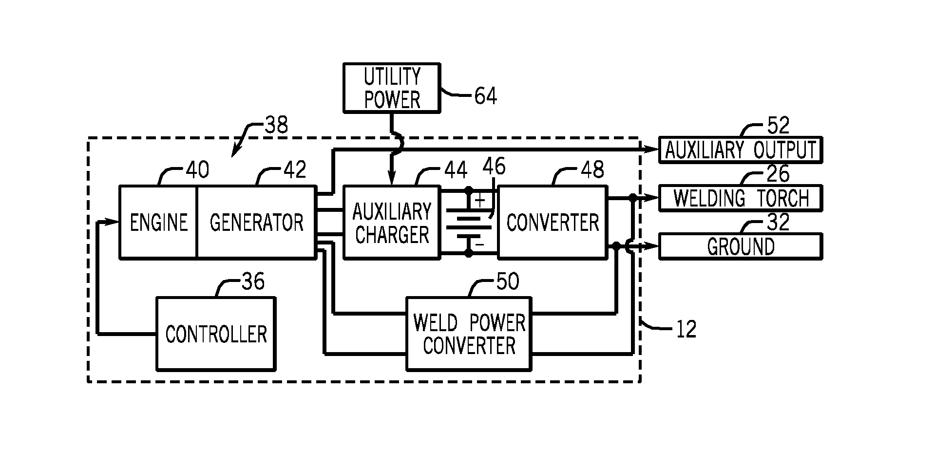
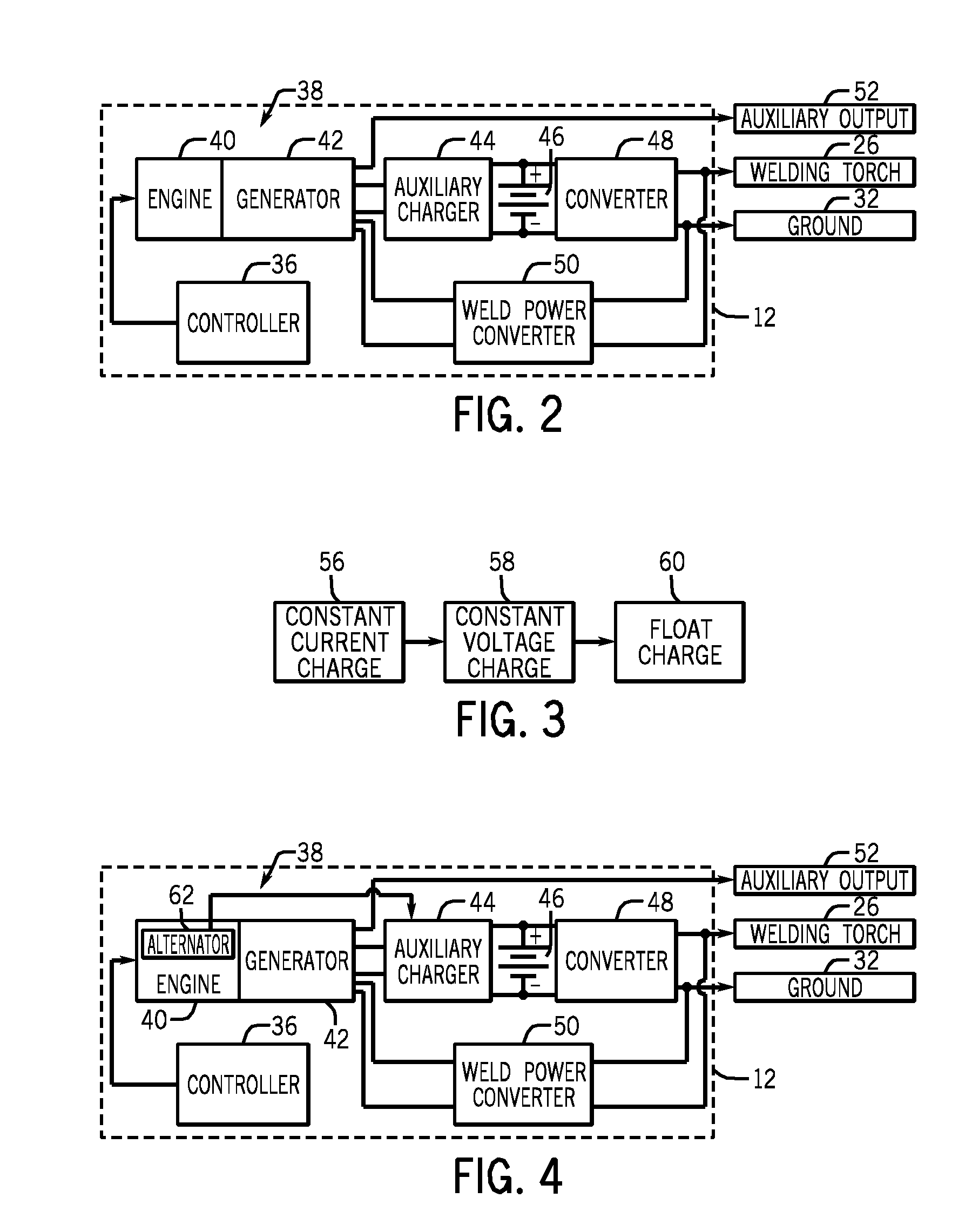
[0014]As described in detail below, embodiments of a welding system having an auxiliary charger are provided. In particular, the auxiliary charger is configured to maintain a float charge of a battery. More specifically, the auxiliary charger maintains the float charge of the battery when power being produced by the battery or generator that is driven by an engine is reduced from a base load. In certain embodiments, the power used by the auxiliary charger to maintain the float charge is received from an alternator of the engine, from a utility power source (e.g., an electrical grid), from an electric system of a work vehicle, or some combination thereof. In certain embodiments, a controller may be used to selectively control which of these power sources are used by the auxiliary charger to maintain the float charge.

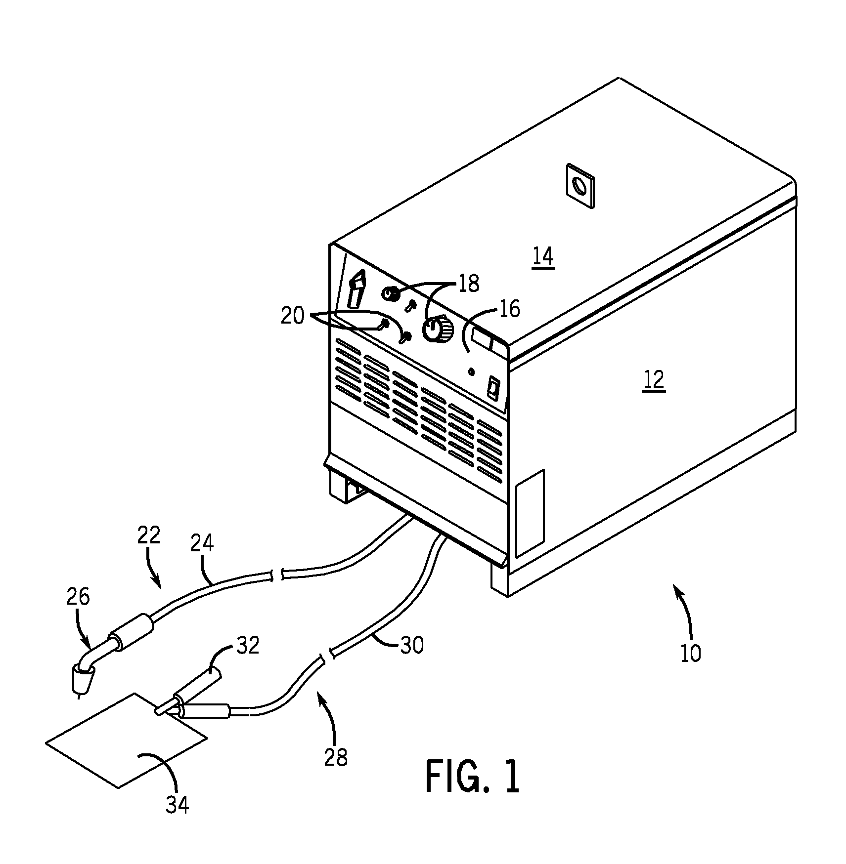
[0015]Turning now to the drawings, FIG. 1 is a perspective view of an exemplary hybrid welding system 10, which functions to power, control, and provide consumables to a ...


PUM

PropertyMeasurementUnit
poweraaaaaaaaaa
poweraaaaaaaaaa
discharge energyaaaaaaaaaa

Abstract

A welding system includes an engine configured to drive a generator to produce a first power output. The welding system also includes a battery configured to discharge energy to produce a second power output. In addition, the welding system includes an auxiliary charger coupled to the battery and the generator. The auxiliary charger is configured to maintain a float charge of the battery when the first and second power outputs are reduced from a base load.

Description

BACKGROUND[0001]The invention relates generally to welding systems, and, more particularly, to hybrid engine-driven welding systems having an auxiliary charger.[0002]Welding is a process that has become increasingly ubiquitous in various industries and applications. As such, a variety of welding applications, such as construction and shipbuilding, may require welding devices that are portable and can easily be transported to a remote welding location. Accordingly, in some cases, it is often desirable for such welding devices to be operable as standalone units remote from a power grid or other primary power source. Therefore, a variety of welding systems utilizing alternate power sources, such as batteries, have been developed. Furthermore, during a welding operation, some weld load demands may be small (e.g., below 150 amps), and to meet such small load demands, the engine-generator unit is activated. However, activation of the engine-generator to meet such small load demands is oft...

Claims


Application Information

Patent Timeline
Patent Type & Authority Applications(United States)
IPC IPC(8): B23K9/10
CPCB23K9/1081B23K9/1075B23K9/1006
Inventor ULRICH, JAMES F.SYKES, ALLEN RAYMOND
Owner ILLINOIS TOOL WORKS INC
Why Eureka
Try Eureka