Organic electroluminescence element and planar light-emitting body
an electroluminescence element and planar light technology, applied in the direction of optical elements, thermoelectric devices, instruments, etc., can solve the problems of reducing the light extraction efficiency and the inability of light emitted from the light-emitting layer to have directivity, and achieve excellent light extraction efficiency and weather resistance.
- Summary
- Abstract
- Description
- Claims
- Application Information
AI Technical Summary
Benefits of technology
Problems solved by technology
Method used
Image
Examples
example 1
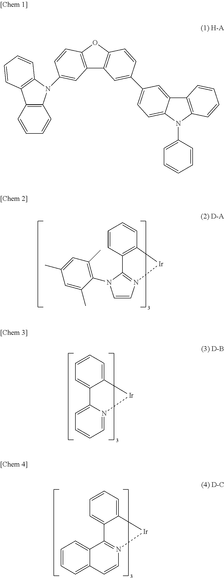
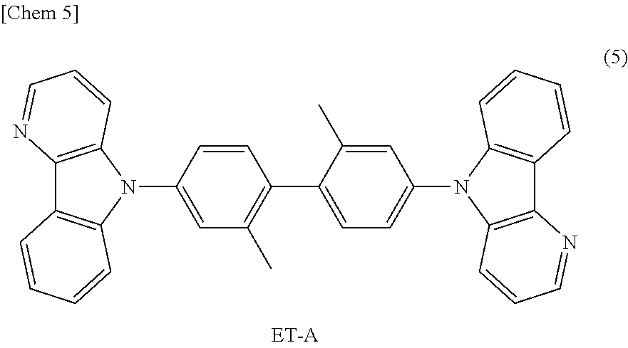
(1) Configuration of Organic EL Element (Examples 1-1 to 1-6)
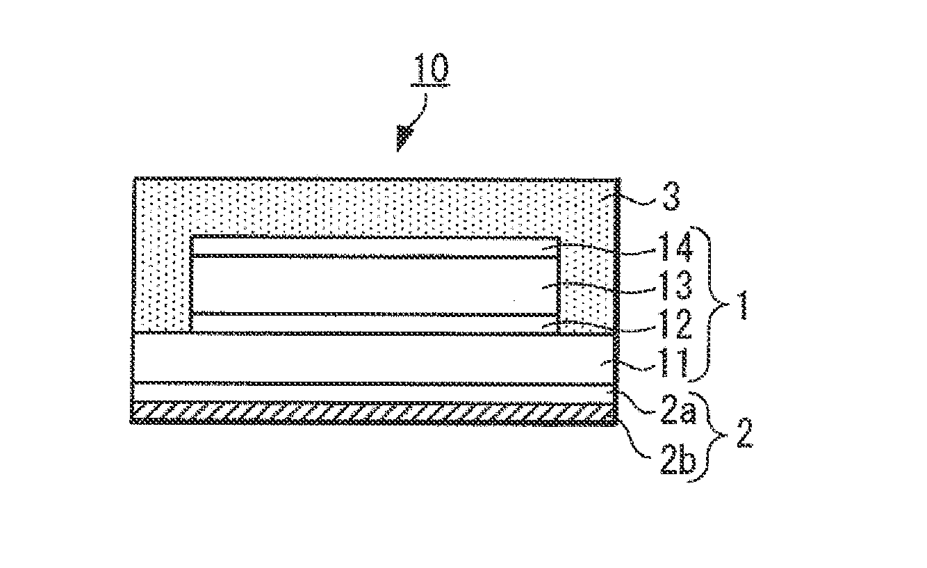
[0269]In Example 1, organic EL elements (Examples 1-1 to 1-6) were produced using each of the fourth to ninth light extraction sheets.
[0270]In addition, in the example, in order to make comparisons with organic EL elements of Examples 1-1 to 1-6, an organic EL element not provided with a light extraction sheet (Comparative Example 1-1) was produced. Furthermore, as Comparative Examples, organic EL elements (Comparative Examples 1-2 to 1-4) were produced using each of the first to third light extraction sheets.
(2) Characteristic Evaluation
[0271]In Example 1, for each of organic EL elements in Examples 1-1 to 1-6 and Comparative Examples 1-1 to 1-4 produced as mentioned above, the following luminance characteristic evaluation was carried out.
[0272]In the luminance characteristic evaluation, first, the luminance when a DC constant current of 2.5 mA / cm2 was flown to each of organic EL elements immediately after the production ...
example 2
(1) Configuration of Organic EL Element (Examples 2-1 to 2-6)
[0282]In Example 2, organic EL elements (Examples 2-1 to 2-6) were produced by changing variously the formation material of the element substrate 31. Meanwhile, in the organic EL elements in Example 2, configurations other than that of the element substrate 31 were set to be the same as the corresponding configurations of the organic EL elements in Example 1-5. That is, in Example 2, the eighth light extraction sheet (sample number 8 of light extraction sheet), in which a concave-convex pattern was formed on the light extraction surface, was used as the light extraction sheet.
[0283]The element substrate 31 used in each of Examples 2-1 to 2-6 is as follows. In the organic EL element in Example 2-1, a PEN (polyethylene naphthalate) film having a thickness of 200 μm was used as the element substrate 31. In the organic EL element in Example 2-2, a PET (polyethylene terephthalate) film having a thickness of 200 μm was used as t...
example 3
[0290]In Example 3, for the respective organic EL elements in Example 1-5, Examples 2-1 to 2-6 and Comparative Examples 2-1 to 2-3, a glow wire heat resistance test was carried out in accordance with a technique described in JIS C8105-1 to examine flame retardance of the respective organic EL elements.
[0291]In FIG. 7, the evaluation results are shown. Meanwhile, the standard of “OK” evaluation and “NG” evaluation of flame retardance shown in FIG. 7 is as follows.
[0292]OK: fire was extinguished within a period shorter than 30 seconds after separation of a glow wire from the organic EL element
[0293]NG: fire was not extinguished even beyond 30 seconds after separation of a glow wire from the organic EL element
[0294]As is clear from FIG. 7, when there is used the light extraction sheet, which has at least a silicon compound added in the light diffusion layer, has a haze value of about 90 or more and has the total light transmittance value of about 80% or more, it was found that the orga...
PUM
 Abstract
Description
Claims
Application Information
 - R&D
- Intellectual Property
- Life Sciences
- Materials
- Tech Scout
- Unparalleled Data Quality
- Higher Quality Content
- 60% Fewer Hallucinations
Browse by: Latest US Patents, China's latest patents, Technical Efficacy Thesaurus, Application Domain, Technology Topic, Popular Technical Reports.
© 2025 PatSnap. All rights reserved.Legal|Privacy policy|Modern Slavery Act Transparency Statement|Sitemap|About US| Contact US: help@patsnap.com


