
Monolithic sun sensors, assemblies thereof, and methods of making and using same

a sun sensor and monolithic technology, applied in the field of sun sensors, can solve the problems of time-consuming mechanical coupling of components for each individual sun sensor, increased mass of sun sensor, and prone to alignment errors of mechanically coupled components, so as to improve the ease of manufacture, reduce the cost of manufacture, and improve the effect of siz

Active Publication Date: 2014-09-18
THE AEROSPACE CORPORATION
View PDF11 Cites 19 Cited by
  • Summary
  • Abstract
  • Description
  • Claims
  • Application Information

AI Technical Summary

Benefits of technology

The present invention provides a new type of sun sensor that is easy to make, smaller, uses less power, is less likely to be positioned incorrectly, and requires less calibration compared to previous methods. This makes it a more efficient and cost-effective solution for detecting sunlight.

Problems solved by technology

Such a mechanical coupling of components for each individual sun sensor may be time-consuming, and practical considerations may require that the components have a size sufficiently large to permit their mechanical handling.
Accordingly, larger sun sensors may require larger power supplies, thus further increasing the mass of the sun sensor.
Furthermore, such mechanically coupled components may be susceptible to alignment errors.
Although each individual sun sensor may be calibrated to reduce such errors, such individual calibration may be relatively time-consuming.
Because of the comparative complexity of manufacturing, assembling, and calibrating such previously known sun sensors, the costs of such sun sensors may be on the order of thousands of dollars or more.

Method used


Image

  • Monolithic sun sensors, assemblies thereof, and methods of making and using same
  • Monolithic sun sensors, assemblies thereof, and methods of making and using same
  • Monolithic sun sensors, assemblies thereof, and methods of making and using same

Examples


Embodiment Construction

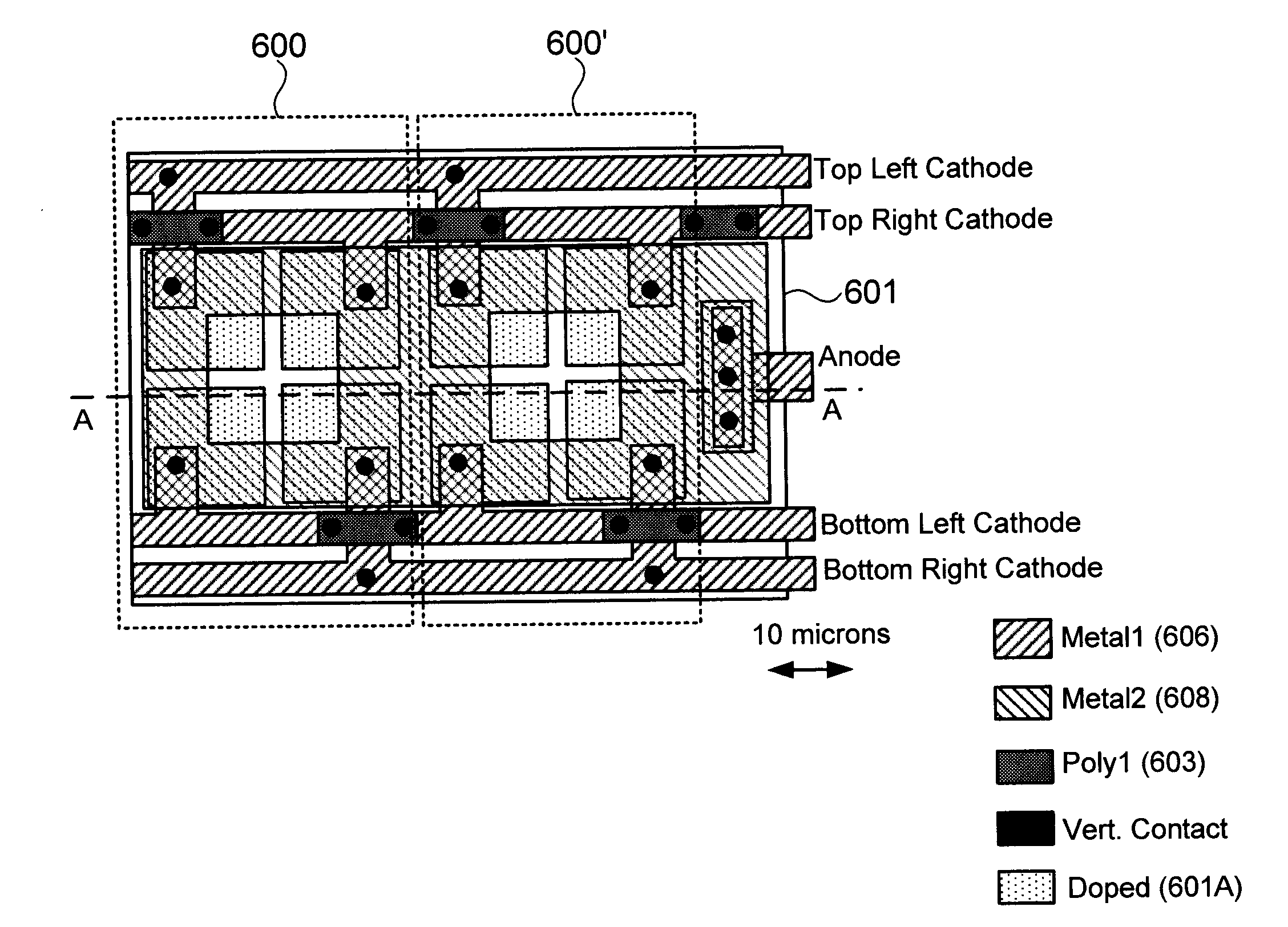
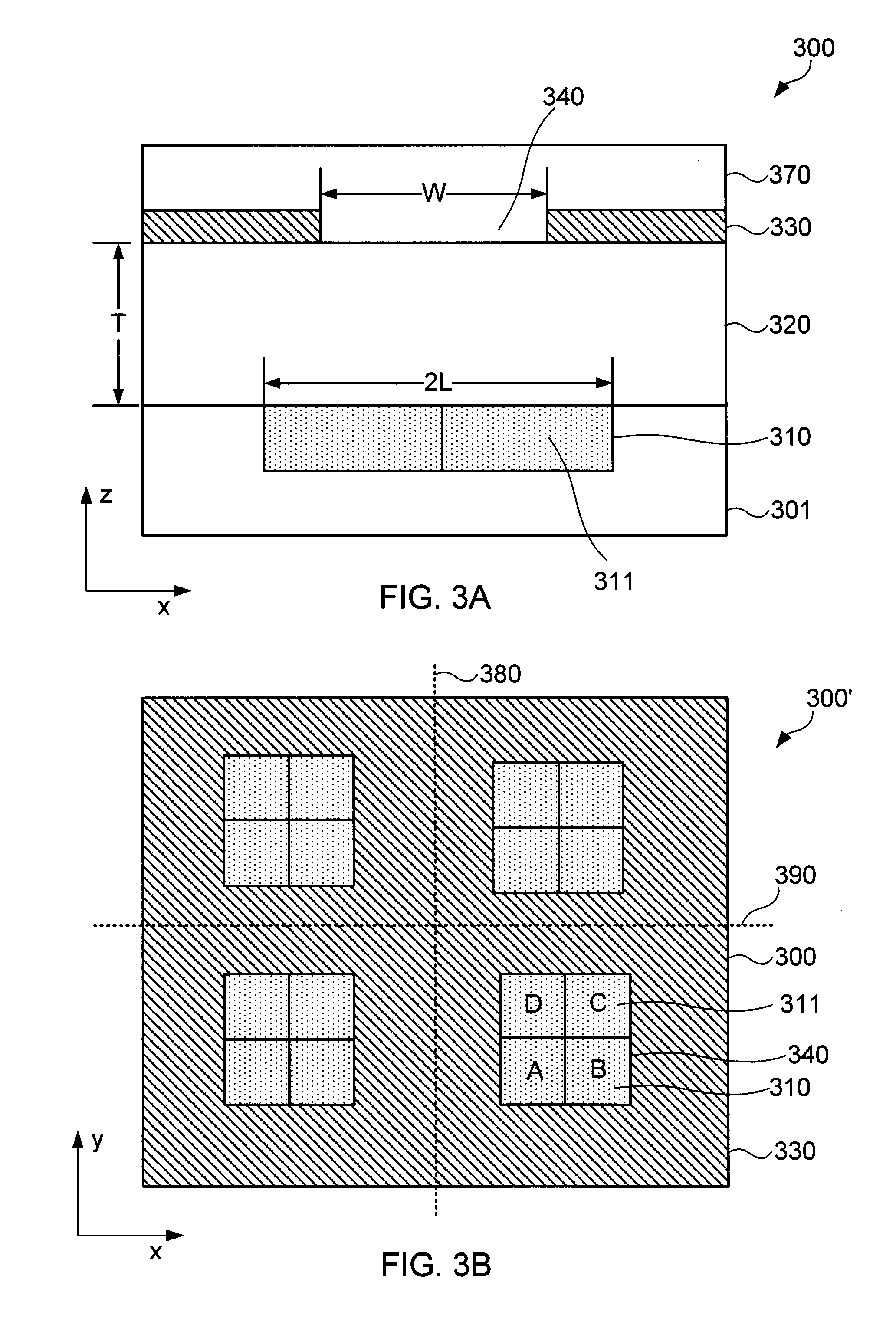
[0023]Embodiments of the present invention provide monolithic sun sensors, assemblies thereof, and methods of making and using same. By “monolithic sun sensor” it is meant a sun sensor in which all components are integrated into a unitary whole, rather than first being individually manufactured and subsequently mechanically coupled together. For example, the monolithic sun sensors provided herein may include a photosensor, a spacer material disposed over the photosensor, and a patterned mask that is disposed over the spacer material and defines an aperture over the photosensor. The thickness of the spacer material may define the distance between the photosensor and the patterned mask, in a manner analogous to that of mechanical spacer 120 described further above with reference to FIG. 1. However, rather than being separately produced and subsequently coupled to (and around) the photosensor, the spacer material provided herein instead may be deposited over the photosensor, thus obvia...


PUM


Abstract

Under one aspect of the present invention, a monolithic sun sensor includes a photosensor; a spacer material disposed over the photosensor; and a patterned mask disposed over the spacer material and defining an aperture over the photosensor. The spacer material has a thickness selected such that the patterned mask casts a shadow onto the photosensor that varies as a function of the monolithic sun sensor's angle relative to the sun. The sun sensor may further include a substrate in which the photosensor is embedded or on which the photosensor is disposed. The spacer material may be transparent, and may include a layer of inorganic oxide, or a plurality of layers of inorganic oxide. The patterned mask may include a conductive material, such as a metal. The aperture may be lithographically defined, and may be square. The sun sensor may further include a transparent overlayer disposed over the patterned mask.

Description

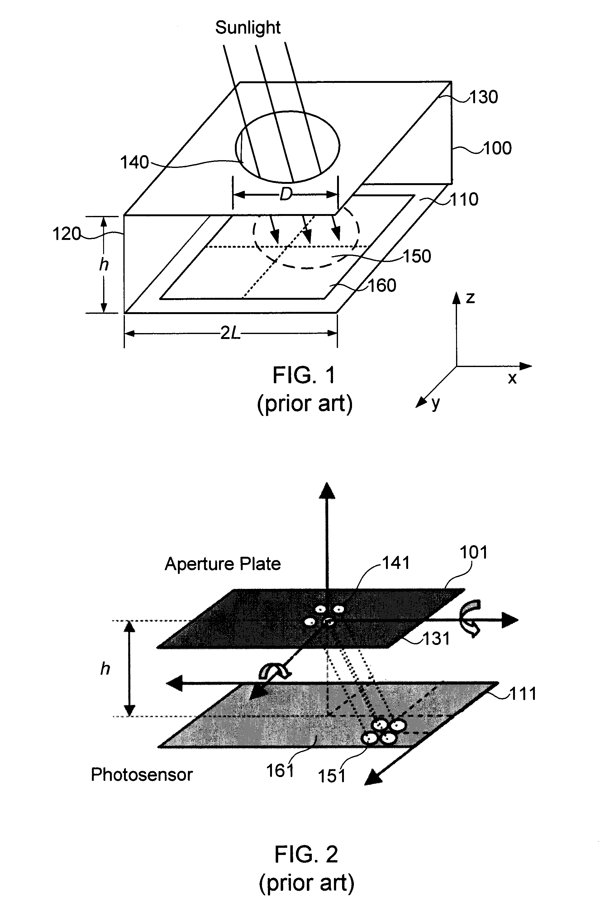
FIELD OF THE INVENTION[0001]This application relates to sun sensors.BACKGROUND OF THE INVENTION[0002]A variety of devices are known for determining the orientation, or attitude, of an object. Such devices may include gyroscopes, motion reference units, horizon sensors, orbital geocompasses, star trackers, and the like. One such category of devices, referred to as sun sensors, are intended to allow the object's angle relative to the sun to be determined based on shadows cast onto a photosensor. For spacecraft such as satellites and space vehicles, which may have relatively unobscured views of the sun during certain periods of the day, sun sensors may provide a convenient and relatively simple way of determining the spacecraft's angle relative to the sun, based on which the attitude of the spacecraft may be controlled.[0003]FIG. 1 schematically illustrates a perspective view of an exemplary previously known sun sensor 100. Sun sensor 100 includes photosensor 110, mechanical spacer 120...

Claims


Application Information

Patent Timeline
IPC IPC(8): G01S3/786H01L31/0216
CPCH01L31/02164G01S3/7861G01J1/0266G01J1/0437G01J2001/4266H01L31/02024
Inventor JANSON, SIEGFRIED W.
Owner THE AEROSPACE CORPORATION
Learn More