Phase detection circuit

a phase detection and circuit technology, applied in the direction of relays, electric devices, instruments, etc., can solve the problems of increasing the load of the remaining phase sources and damage to the multi-phase power supply

Inactive Publication Date: 2014-09-18
SCIENBIZIP CONSULTINGSHENZHENCO
View PDF3 Cites 8 Cited by
  • Summary
  • Abstract
  • Description
  • Claims
  • Application Information

AI Technical Summary

Problems solved by technology

However, if one phase source of the multi-phase power supply fails to work properly, a conventional detecting circuit cannot detect the abnormal phase source, the multi-phase power supply will continue to work, thereby increasing the load to the remaining phase sources, which could damage the multi-phase power supply.

Method used


Image

  • Phase detection circuit
  • Phase detection circuit
  • Phase detection circuit

Examples


Embodiment Construction

[0009]The disclosure is illustrated by way of example and not by way of limitation in the figures of the accompanying drawings in which like references indicate similar elements. It should be noted that references to “an” or “one” embodiment in this disclosure are not necessarily to the same embodiment, and such references mean “at least one.” The reference “a plurality of” means “at least two.”

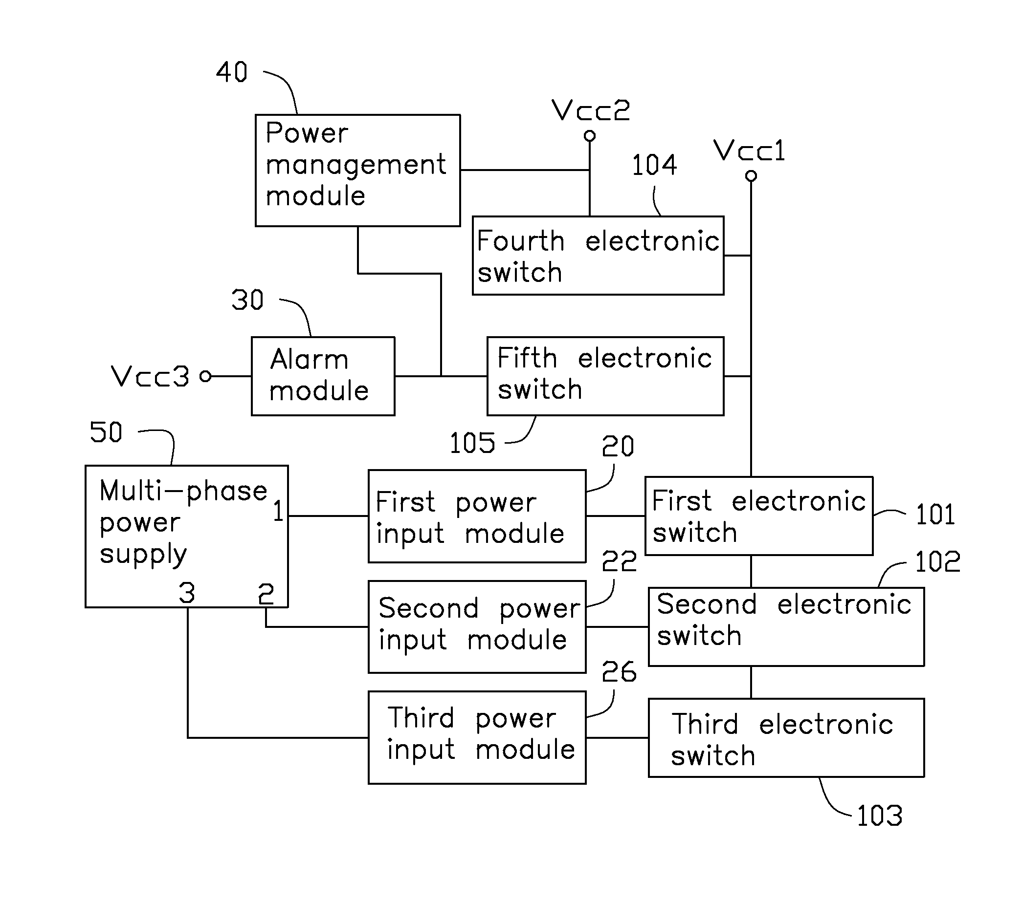
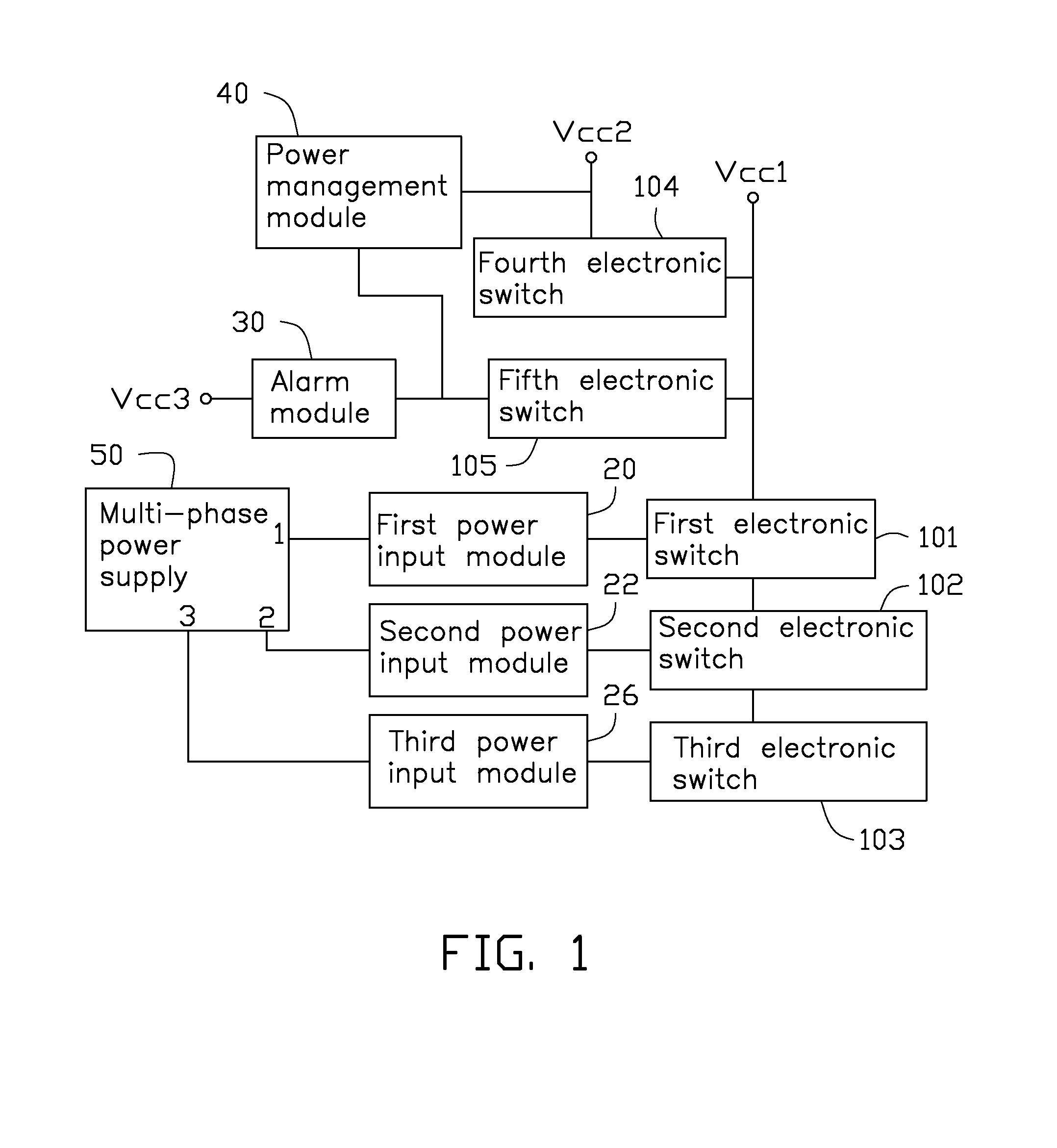
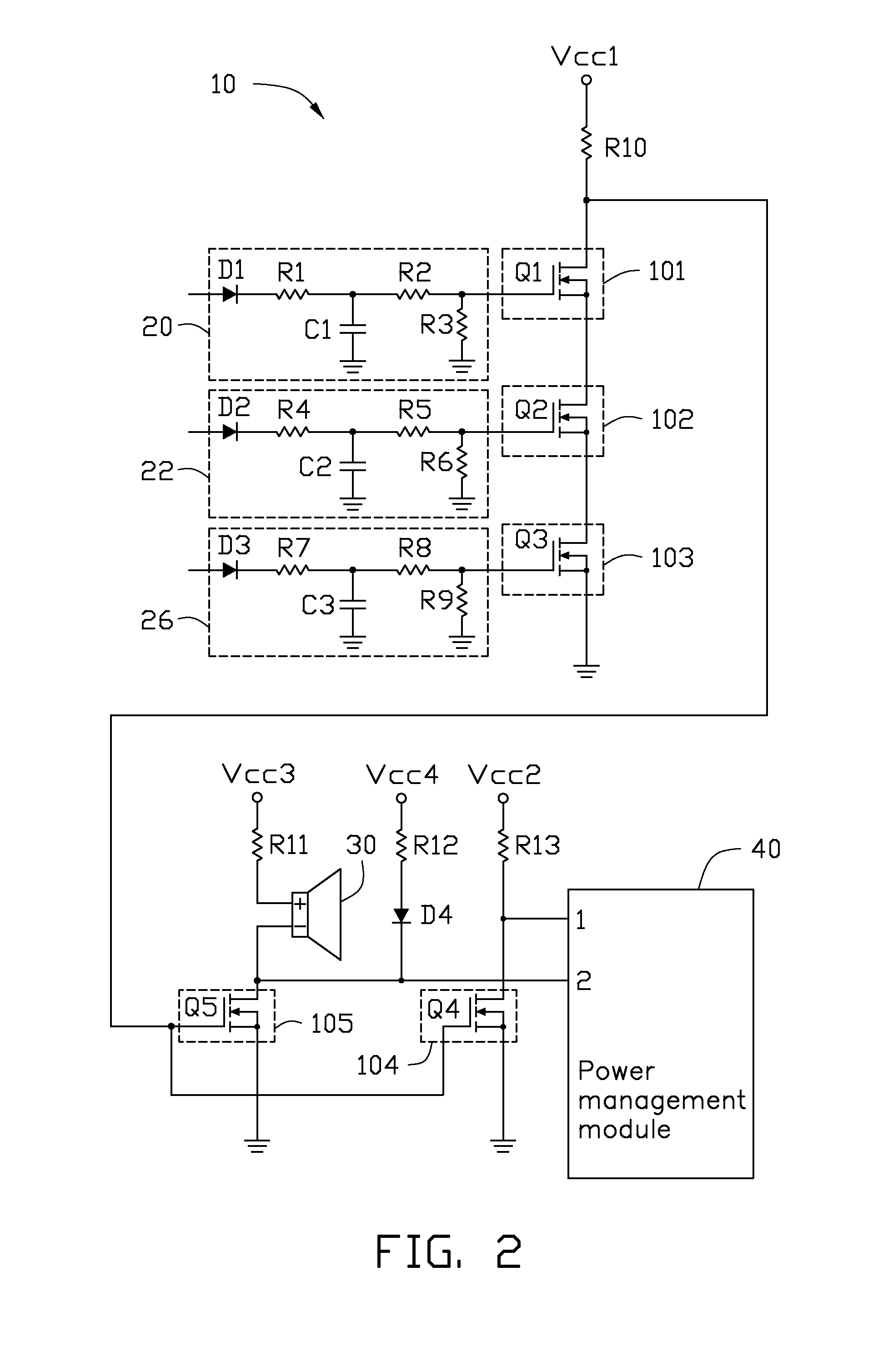
[0010]FIGS. 1 and 2 show an embodiment of a phase detection circuit 10 of the present disclosure.

[0011]The phase detection circuit 10 is used to detect a multi-phase power supply 50. In the embodiment, the multi-phase power supply 50 has first to third phase output terminals 1-3. The phase detection circuit 10 comprises a first power input module 20, a second power input module 22, a third power input module 26, first to third power input terminals Vcc1-Vcc3, an alarm module 30, first to fifth electronic switches 101-105, and a power management module 40. The first to third power input termin...


PUM


Abstract

A phase detection circuit includes first to third power input modules, first to third power input terminals, an alarm module, first to fifth electronic switches, and a power management module. The power input modules are used to convert pulse signals from a multi-phase power supply into direct current voltages and output the direct current voltages to the first to third electronic switches. When the multi-phase power supply operates abnormally, no direct current voltages are output to the first to third electronic switches and the alarm module alarms.

Description

BACKGROUND[0001]1. Technical Field[0002]The present disclosure relates to a phase detection circuit.[0003]2. Description of Related Art[0004]Many electronic devices have energy-saving control functions using multi-phase power supply. However, if one phase source of the multi-phase power supply fails to work properly, a conventional detecting circuit cannot detect the abnormal phase source, the multi-phase power supply will continue to work, thereby increasing the load to the remaining phase sources, which could damage the multi-phase power supply.[0005]Therefore, there is room for improvement in the art.BRIEF DESCRIPTION OF THE DRAWINGS[0006]Many aspects of the present disclosure can be better understood with reference to the following drawing(s). The components in the drawing(s) are not necessarily drawn to scale, the emphasis instead being placed upon clearly illustrating the principles of the present disclosure. Moreover, in the drawing(s), like reference numerals designate corre...

Claims


Application Information

Patent Timeline
Patent Type & Authority Applications(United States)
IPC IPC(8): H02J1/00G01R21/00
CPCH02J1/00G01R21/00H02H11/004H02H3/265Y10T307/747
Inventor ZHOU, HAI-QINGTU, YI-XIN
Owner SCIENBIZIP CONSULTINGSHENZHENCO
Why Eureka
Try Eureka