Electromechanical transducer and electrocoustic transducer

a transducer and electromechanical technology, applied in the direction of transducer details, electrical transducers, dynamo-electric machines, etc., can solve the problems of difficult to increase the yield stress of the armature by heat treatment, difficult to use general spring materials with large yield stress and strong shock resistance, and difficult to achieve the effect of improving the degree of freedom in designing the armatur

Active Publication Date: 2014-09-18
RION COMPANY
View PDF2 Cites 13 Cited by
  • Summary
  • Abstract
  • Description
  • Claims
  • Application Information

AI Technical Summary

Benefits of technology

[0010]According to the electromechanical transducer of the invention, when no current flows in the coil, the armature is initially in a state of being positioned at a predetermined position of an internal space of the structural unit including a through hole of the coil, and the armature is relatively displaced by magnetic forces applied to the inner portion due to a current flowing in the coil. Then, each of the two elastic members gives a restoring force being proportional to amount of the displacement of the armature and having a direction reverse to that of the displacement. Thus, since the structure for utilizing the restoring force of the two elastic members attached to both ends of the armature, without utilizing elasticity of the armature itself, it is possible to improve the degree of freedom in designing the armature. That is, since a sufficient amount of displacement can be obtained without thinning thickness of the armature, it is possible to improve the shock resistance of the magnetic circuit.
[0014]The invention may comprise protectors that limit range of movement of the armature relative to the structural unit, which are located in vicinities of the first and second outer portions of the armature in the structural unit. Thereby, it is possible to take effective measures against plastic deformation caused by a shock of the spring members.
[0017]As described above, according to the present invention, the pair of elastic members connecting between both ends of the armature and the structural unit is provided in order to give the restoring force for the displacement of the armature, without utilizing the elasticity of the armature itself, thereby improving degree of freedom in designing the armature. This structure enables both excellent magnetic characteristics and shock resistance, and it is possible to achieve a small-scale and high-power electromechanical transducer and / or electroacoustic transducer.

Problems solved by technology

However, if the thickness of the armature is increased, it is not possible to obtain sufficient amount of displacement within an elasticity range of the armature.
Further, since the armature is required to have necessary magnetic property, it is difficult to use general spring material having large yield stress and strong shock resistance.
In general, magnetic annealing treatment is performed for the armature after forming process for the purpose of extracting the magnetic property of its material, and therefore it is also difficult to increase the yield stress of the armature by heat treatment.
As described above, according to the conventional structure, it is inevitable that degree of freedom in designing the armature is largely restricted.

Method used


Image

  • Electromechanical transducer and electrocoustic transducer
  • Electromechanical transducer and electrocoustic transducer
  • Electromechanical transducer and electrocoustic transducer

Examples


first embodiment

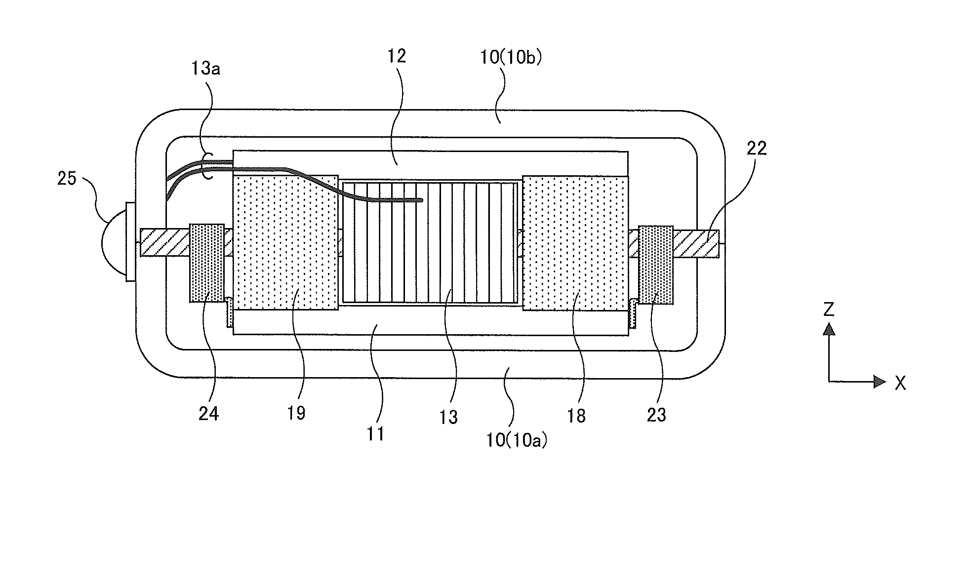
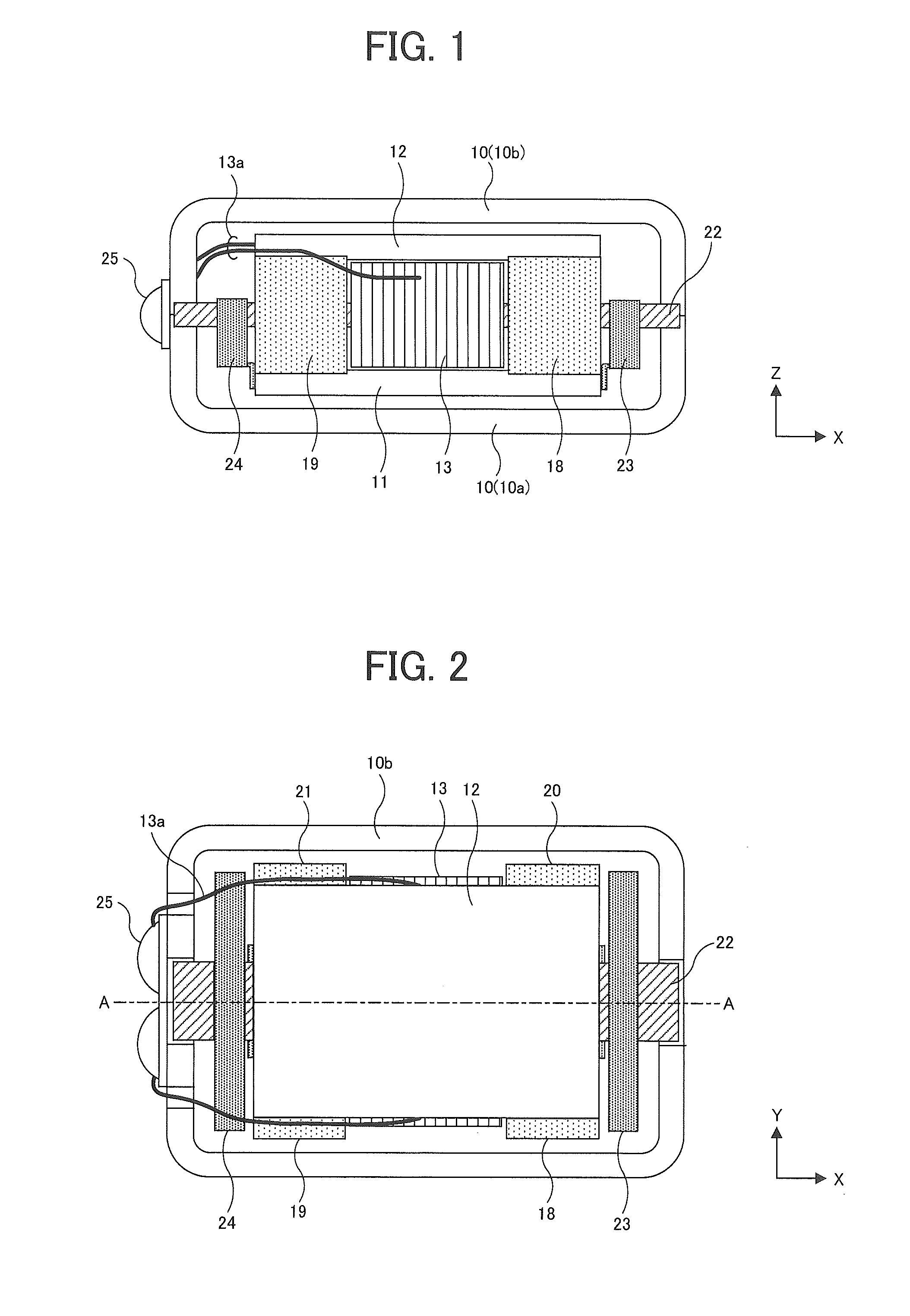
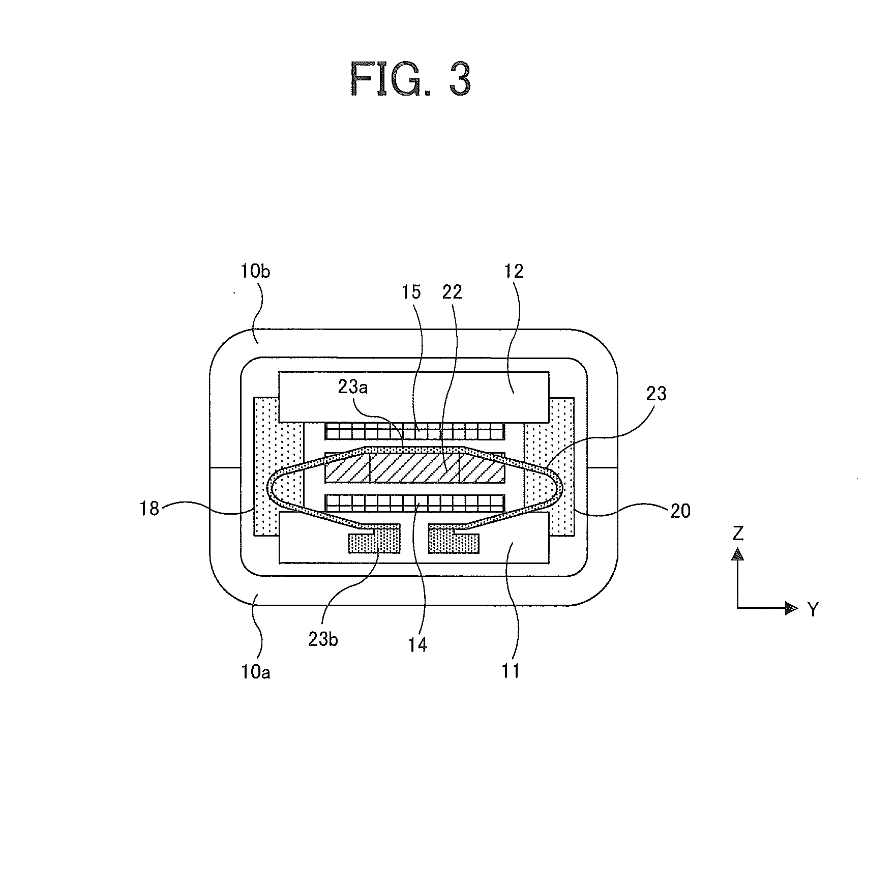
[0039]An electromechanical transducer of a first embodiment of the present invention will be described with reference to FIGS. 1 to 5. FIG. 1 is a partially cutaway end view (front view) showing an internal structure of the electromechanical transducer of the first embodiment. On the right side of FIG. 1, an X direction and a Z direction are indicated by arrows, respectively. FIG. 2 is a partially cutaway end view (top view) showing the electromechanical transducer of FIG. 1 as viewed from the upper side of the figure along the Z direction, in which the X direction and a Y direction are indicated by arrows, respectively. FIG. 3 is a partially cutaway end view (right side view) showing the electromechanical transducer of FIG. 1 as viewed from the right side of the figure along the X direction, in which the X direction and the Y direction are indicated by arrows, respectively. FIG. 4 is an exploded perspective view of a later-described magnetic circuit portion in the electromechanical...

second embodiment

[0067]Next, an electromechanical transducer of a second embodiment of the present invention will be described with reference to FIGS. 8 and 9. Most of the structure of the electromechanical transducer of the second embodiment is common to that of the first embodiment, and thus different points will be mainly described hereinafter. FIG. 8 is a top view (partially cutaway end view) showing the structure of the electromechanical transducer of the second embodiment, and FIG. 9 is a cross-sectional structural view along an A-A cross section of FIG. 8. FIGS. 8 and 9 correspond to FIGS. 2 and 5 of the first embodiment, respectively, in which the directions represented by X, Y and Z are also common.

[0068]In the electromechanical transducer of the second embodiment, constituent elements that are substantially the same as those in the first embodiment are denoted by the same symbols. Meanwhile, in the electromechanical transducer of the second embodiment, there are provided four yokes 40, 41,...

third embodiment

[0072]Next, an electromechanical transducer of a third embodiment of the present invention will be described with reference to FIGS. 10 to 13. Most of the structure of the electromechanical transducer of the third embodiment is common to that of the first embodiment, and thus different points will be mainly described hereinafter. FIG. 10 is a front view (partially cutaway end view) showing the structure of the electromechanical transducer of the third embodiment, FIG. 11 is a top view (partially cutaway end view) as viewed from the upper side of FIG. 10, FIG. 12 is a right side view (partially cutaway end view) as viewed from the right side of FIG. 10, and FIG. 13 is an exploded perspective view of a magnetic circuit portion in the electromechanical transducer of the third embodiment. FIGS. 10 to 13 correspond to FIGS. 1 to 4 of the first embodiment, respectively, in which the directions represented by X, Y and Z are also common. In addition, a cross-sectional structural view along ...


PUM


Abstract

An electromechanical transducer of the invention comprises a structural unit, an armature, and first and second elastic members. The structural unit includes at least one pair of magnets, a yoke conducting a magnetic flux generated by the magnets, and a coil supplied with an electric signal. The armature has an inner portion disposed to pass through an internal space of the structural unit and first and second outer portions protruding on both sides from the inner portion, and the armature constitutes a magnetic circuit with the structural unit via two regions through which components of the magnetic flux flow in directions opposite to each other in the inner portion. The first and second elastic members connect between the first and second outer portions of the armature and the structural unit, respectively.

Description

BACKGROUND OF THE INVENTION[0001]1. Field of the Invention[0002]The present invention relates to an electromechanical transducer that transduces an electric signal into mechanical vibration and an electroacoustic transducer that transduces an electric signal into sound, and particularly relates to an electromechanical transducer and an electroacoustic transducer that comprise a driving unit including an armature, a yoke, a coil and magnets.[0003]2. Description of Related Art[0004]An electroacoustic transducer used in a hearing aid or the like is provided with a driving unit including an armature, a yoke, a coil and a pair of magnets, etc., and is configured to drive the armature in response to an electric signal supplied to the coil so that relative vibration between the armature and other members is transduced into sound. For example, as examples of a so-called balanced armature type (hereinafter, referred to as “balanced type”) electromagnetic transducer, Patent Reference 1 disclo...

Claims


Application Information

Patent Timeline
Patent Type & Authority Applications(United States)
IPC IPC(8): H04R1/00H02K35/06
CPCH02K35/06H04R1/00H04R11/02H04R2460/13H04R11/00
Inventor IWAKURA, TAKASHIDATE, MUNEHIRO
Owner RION COMPANY
Why Eureka
Try Eureka