Multi- purpose apparatus for switching, amplifying, replicating, and monitoring optical signals on a multiplicity of optical fibers

a multi-purpose, optical fiber technology, applied in electrical apparatus, instruments, optics, etc., can solve the problems of software that must eventually reach the bottom, inefficiency and associated excess cost, and the huge matrices of optical fiber distribution systems, so as to introduce undesired excess optical losses

Inactive Publication Date: 2014-09-18
MILLER GARY EVAN +1
View PDF53 Cites 9 Cited by
  • Summary
  • Abstract
  • Description
  • Claims
  • Application Information

AI Technical Summary

Benefits of technology

[0019]Another purpose of this disclosure is to describe how these functions can be accomplished in a substantially smaller physical space than current

Problems solved by technology

The various origination, termination, and relay points for optical fiber distribution systems form huge matrices—much more complicated than, say, a map of the railroads or the electrical power grid infrastructures in the United States and abroad.
However, this software must eventually reach down to actual hardware such as optical fibers, lasers, photodetectors, and optical switches.
While the use of N×N optical switches for directing tapped signals to a mon

Method used


Image

  • Multi- purpose apparatus for switching, amplifying, replicating, and monitoring optical signals on a multiplicity of optical fibers
  • Multi- purpose apparatus for switching, amplifying, replicating, and monitoring optical signals on a multiplicity of optical fibers
  • Multi- purpose apparatus for switching, amplifying, replicating, and monitoring optical signals on a multiplicity of optical fibers

Examples


Embodiment Construction

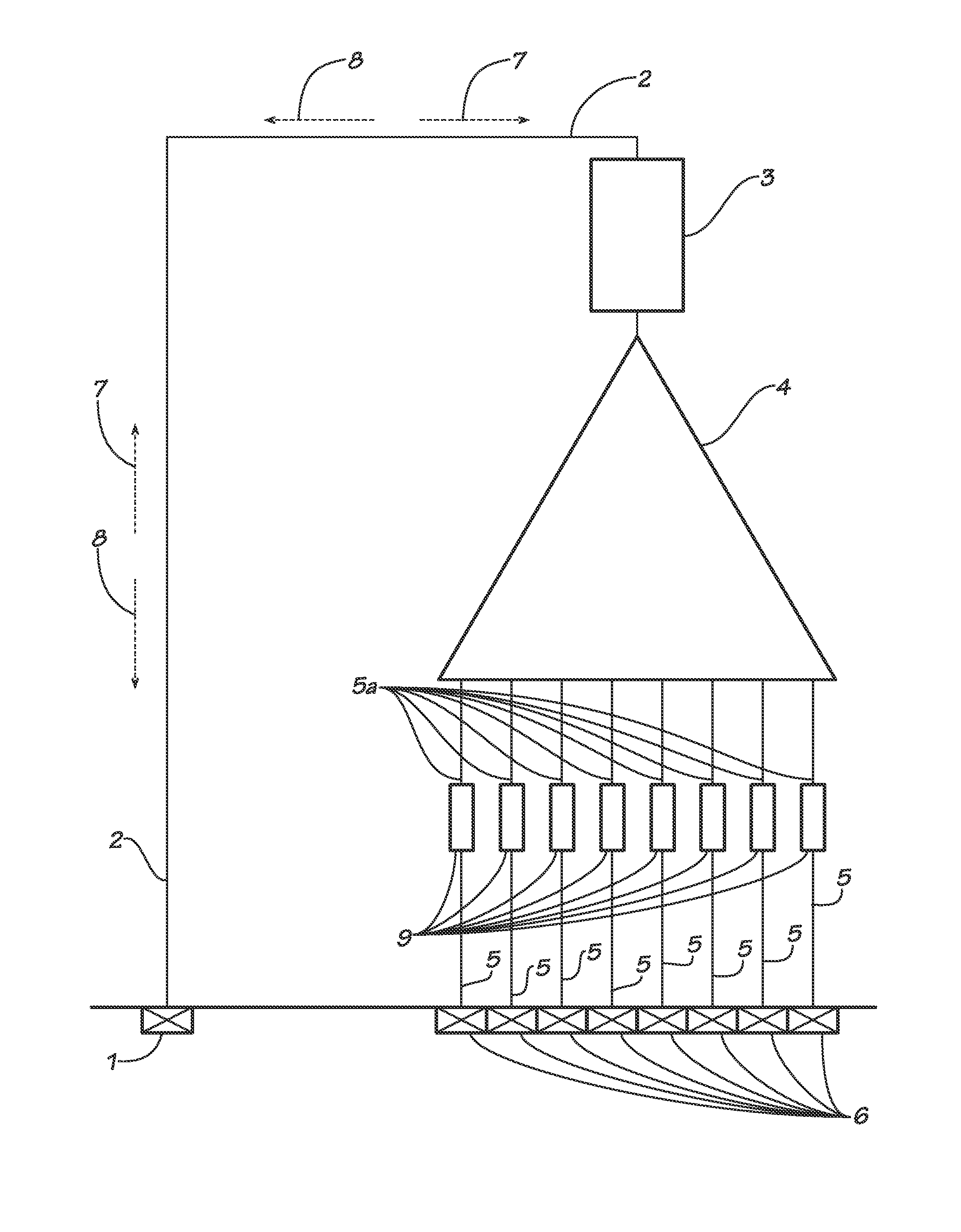
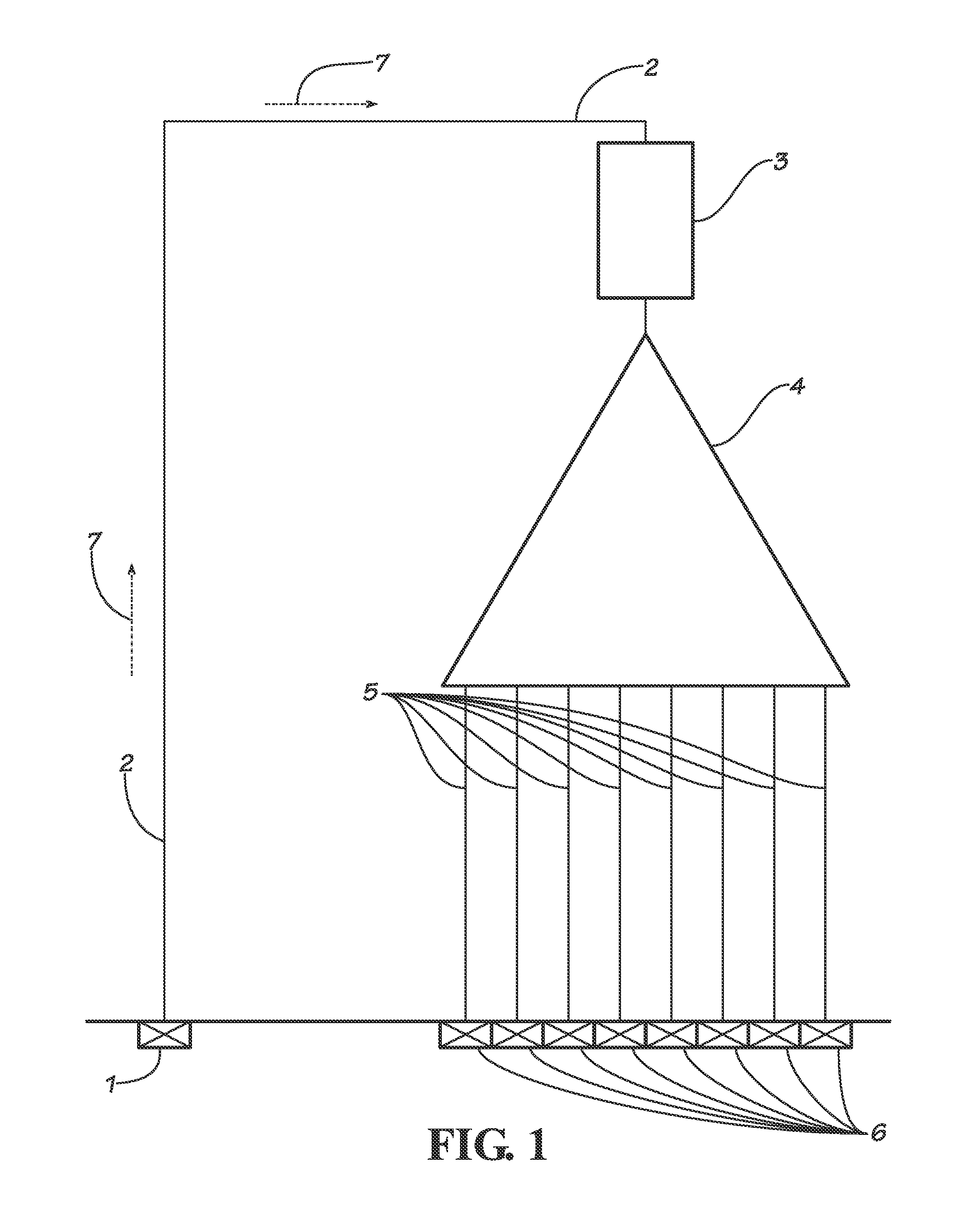
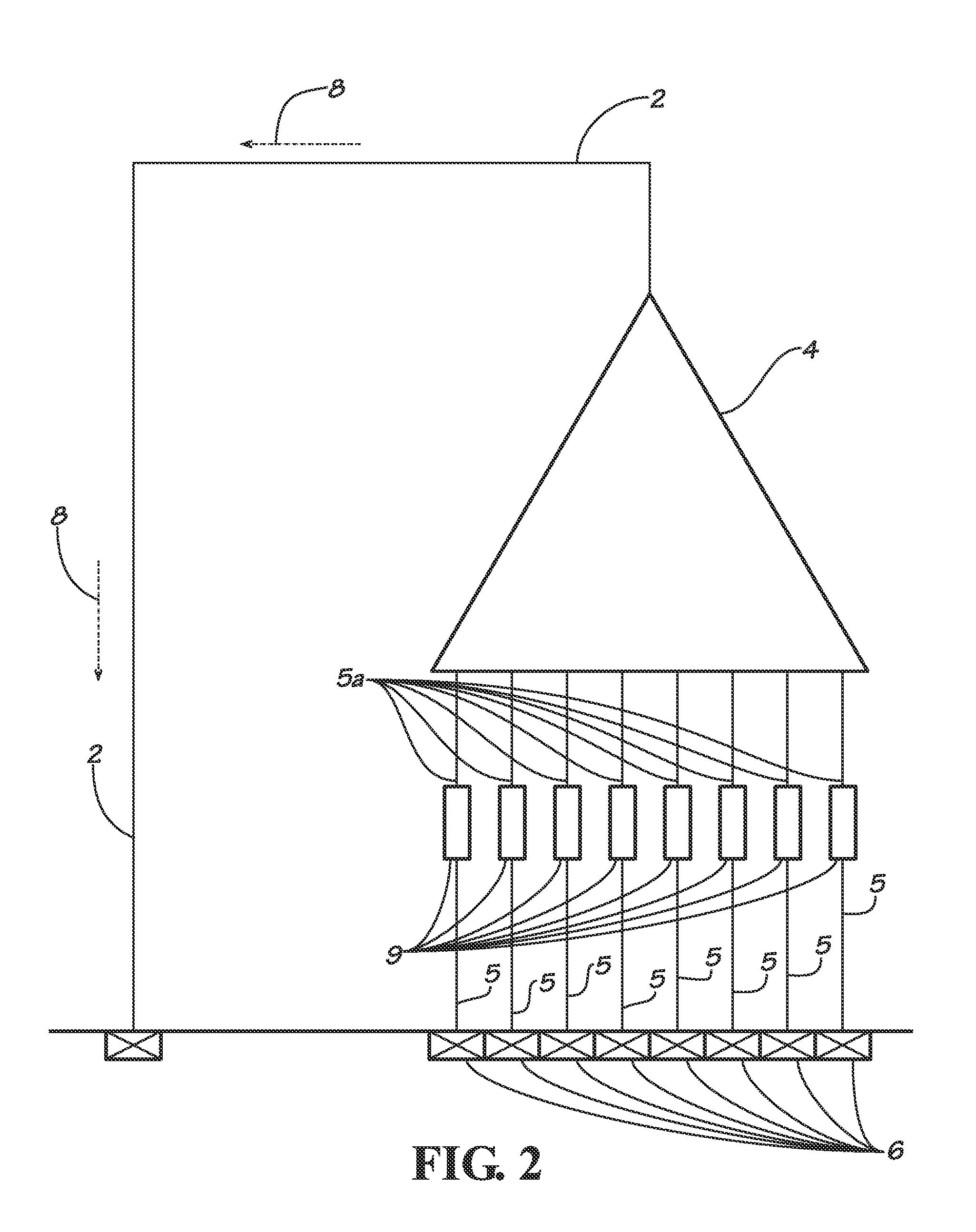
[0028]Several useful functions that are included in many modern day fiber optical communication systems are (1) replication of an optical signal on a single optical fiber onto a multiplicity of optical fibers, (2) amplification of optical signals, and (3) sequential switching of optical signals on a large number of optical fibers to a single or limited number of optical fibers that can each be connected to specialized performance monitoring equipment. All of these functions can be accomplished using a single apparatus called a Switch, Amplifier, Replicator, Monitoring apparatus or, simply a SwARM unit that can manage as few as 8 optical fibers up to 512 optical fibers, or more by multiplexing. With reference to the attached drawings, embodiments of the present invention will be described below.

[0029]FIG. 1 shows a block diagram of an optical splitter circuit including an optical amplifier 3 that can be used to replicate an optical signal on a single input optical fiber 2 onto a mult...


PUM


Abstract

Several useful functions that are included in many modern day fiber optical communication systems are (1) replication of an optical signal on a single optical fiber onto a multiplicity of optical fibers, (2) amplification of optical signals, and (3) sequential switching of optical signals on a large number of optical fibers to a single or limited number of optical fibers that can each be connected to specialized performance monitoring equipment. These functions can be accomplished using a single apparatus called a multi-purpose Switched, Amplifying, Replicating and Monitoring apparatus that can manage as few as 8 optical fibers up to 512 optical fibers, or more by multiplexing.

Description

CROSS-REFERENCES TO RELATED APPLICATIONS[0001]This application claims the benefit of U.S. Provisional Patent Application Ser. No. 61 / 851,968 filed Mar. 13, 2013, the contents of which are hereby incorporated by reference herein.TECHNICAL FIELD AND INDUSTRIAL APPLICABILITY OF THE INVENTION[0002]The present invention relates to accomplishing the following three different functions that are required in many modern day fiber optical communication systems with a single innovative optical circuit: (1) replication of an optical signal on a single optical fiber onto a multiplicity of optical fibers, (2) amplification of optical signals, and (3) sequential switching of optical signals on a large number of optical fibers to a single or limited number of optical fibers that can each be connected to specialized performance monitoring equipment.BACKGROUND OF INVENTION[0003]Terrestrial communications throughout the world has grown to rely heavily on optical fiber communications technology. And th...

Claims


Application Information

Patent Timeline
IPC IPC(8): G02B6/35
CPCG02B6/35H04Q11/0005H04Q2011/0016H04Q2011/0035
Inventor MILLER, GARY EVANJOHNSTON, OTIS JAMES
Owner MILLER GARY EVAN
Why Eureka
Try Eureka