System and method for generating auditory spatial cues

Active Publication Date: 2007-10-04
OTICON
View PDF6 Cites 167 Cited by
  • Summary
  • Abstract
  • Description
  • Claims
  • Application Information

AI Technical Summary

Benefits of technology

[0013]A particular advantage of the present invention is the provision of a hearing aid wherein the introduction of new auditory spatial cues require very little processing time and thus require very little physical space on a signal processing chip.
[0014]The above objects and advantage together with numerous other objects, advantages and features, which will become evident from below detailed description, are obtained according to a first aspect of the present invention by a hearing aid system for generating auditory spatial cues and comprising a first microphone unit adapted to convert sound received at a first microphone to a first electric signal on a first output and received at a second microphone to a second electric signal on a second output, a first delay unit connected to said first output and adapted to delay said first electric signal, a first calculation unit connected to said first delay unit and said second output and adapted to sum said delayed first electric signal and said second electric signal and to generate a first summed signal, a processor unit connected to said first calculation unit and adapted to process said first summed signal and to generate a processed signal, and a speaker a

Problems solved by technology

However, if the auditory spatial cues occur in a frequency range where the person has a hearing impairment this affects the person's ability to determine the location of sound sources.
Not only may the auditory spatial cues be inaudible due to having insufficient intensity to overcome the listener's hearing threshold, but the reduced perceptual frequency resolution which often accompanies hearing impairment may also cause the cues to lose distinctness and thus utility.
However, the international patent application fails to disclose an acoustic receiver compensating for the perceptual degradation of spatial hearing suffered by a listener with a hearing impairment.
However, the hearing

Method used


Image

  • System and method for generating auditory spatial cues
  • System and method for generating auditory spatial cues
  • System and method for generating auditory spatial cues

Examples


first embodiment

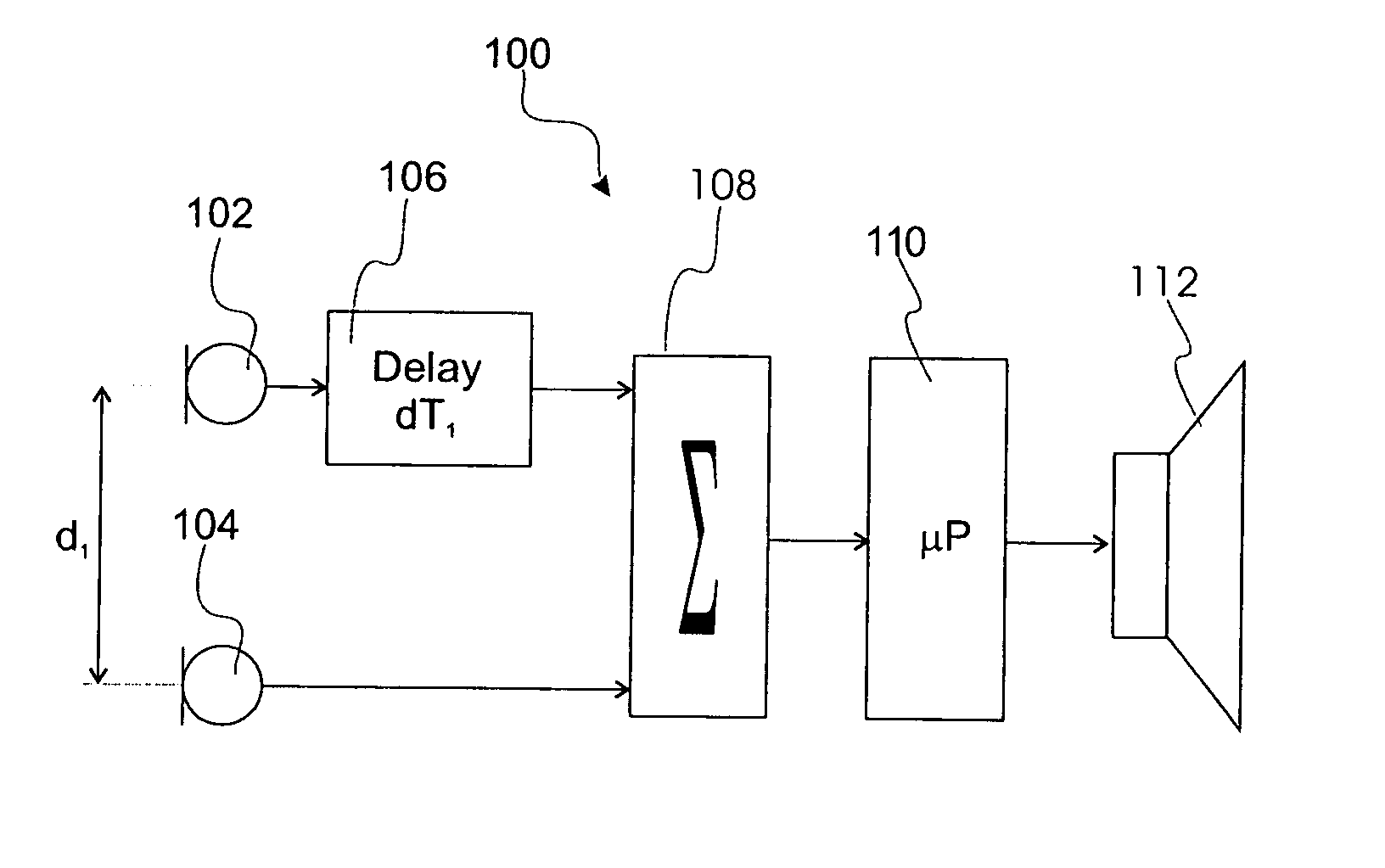
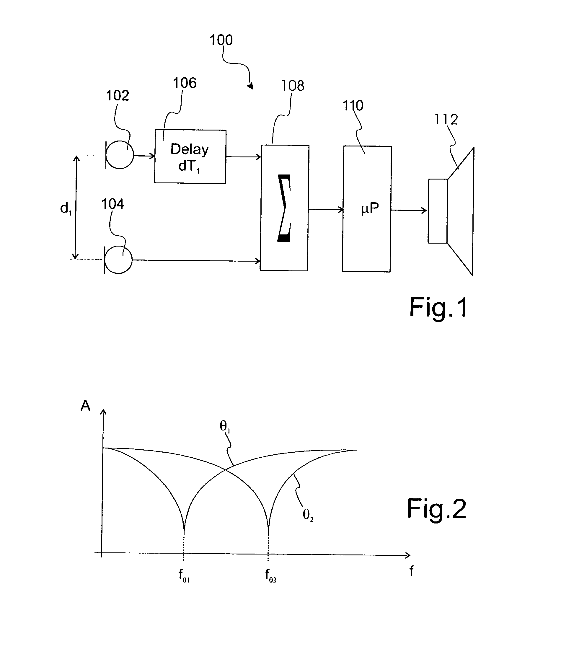
[0041]FIG. 1 shows a hearing aid system according to the present invention and designated in entirety by reference numeral 100. The hearing aid system 100 comprises a first and second microphone 102 and 104 for converting the sound into a first and second electric signal, respectively. The first and second microphones 102 and 104 are separated by a distance d, between the centers of the membranes of the first and second microphones 102 and 104.

[0042]The first electric signal is time delayed by a delay unit 106 before being communicated to a first calculation unit 108, which weights and sums the delayed first electric signal and the second electric signal. By positioning of the first and second microphones 102, 104 relative to one another by the distance d1 and by adjusting the time delay of the first electric signal the output of the first calculation unit 108 provides a first auditory spatial cue, which in case of movement of the sound source shifts up and down in the frequency spe...

second embodiment

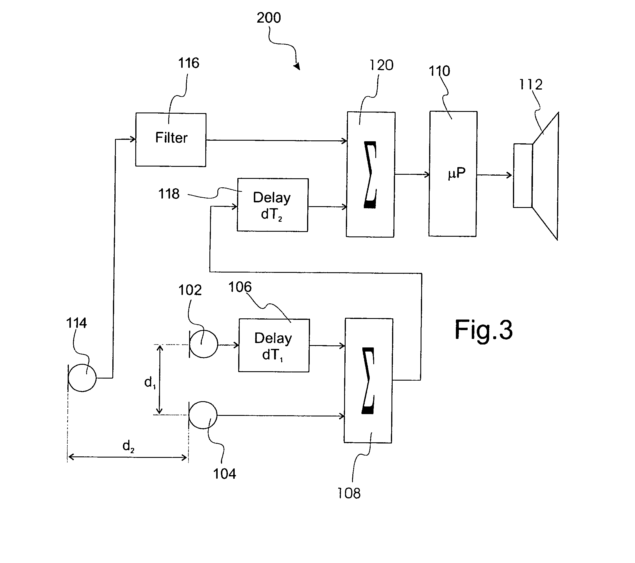
[0046]FIG. 3 shows a hearing aid system according to the present invention and designated in entirety by reference numeral 200. The hearing aid system 200 comprises some of the elements of the hearing aid system 100, which elements are referenced using the same reference numerals.

[0047]The hearing aid system 200 comprises a third microphone 114 separated perpendicularly relative to the axis of the first and second microphones 102, 104 by a distance d2. The third microphone 114 converts the sound to a third electric signal, which is forwarded to a filter 116 with for example a low-pass cut-off frequency lying for example between 2 kHz and 4 kHz thereby avoiding the occurrence of auditory cues above the cut-off frequency to ensure that the first elevation auditory cue provided by microphones 102 and 104 is not disturbed.

[0048]In one particular embodiment the first and second microphones 102 and 102 may be placed on a behind-the-ear component of a hearing aid, while the third microphon...

third embodiment

[0050]FIG. 4 shows a hearing aid system according to the present invention and designated in entirety by reference numeral 300. It should be understood that the hearing aid system 300 may incorporate features of the hearing aid systems designated 100 and 200.

[0051]The hearing aid system 300 comprises a first and second hearing aid 302 and 304. The first hearing aid 302 comprises elements of hearing aid systems 100 and 200, that is, comprises a first microphone unit 306 generating a first, second and / or third electric signal from a sound. These signals are communicated to a first auditory cue generator 308 generating an elevation auditory cue and / or a front / back auditory cue in a first summed signal communicated to a first processing unit 310 performing the, normally, required processing operations in accordance with sound and hearing impairment of the user before communicating a processed signal to a speaker 312.

[0052]The second hearing aid 304 similarly comprises elements of hearin...


PUM


Abstract

This invention relates to a hearing aid system (100, 200, 300) for generating auditory spatial cues. The hearing aid system (100, 200, 300) comprises a first microphone unit (306) adapted to convert sound received at a first microphone (102) and received at a second microphone (104), a first delay unit (106) connected to the first microphone (102) delaying the signal from the first microphone (102), a first calculation unit (108) for summing the delayed signal of the first microphone (102) and signal of the second microphone (104), a processor unit (110) processing the summed signal, and a speaker converting the processed signal to a processed sound. The first and second microphones (102, 104) are separated by a predetermined first distance and the first delay unit (106) provides a predetermined first delay thereby generating a first auditory spatial cue representing a first spatial dimension in the summed signal.

Description

FIELD OF INVENTION[0001]This invention relates a system and method for generating auditory spatial cues. In particular, this invention relates to a hearing aid such as a behind-the-ear (BTE), in-the-ear (ITE), completely-in-canal (CIC), receiver-in-the-ear (RITE), middle-ear-implant (MEI) or cochlear implant (CI), wherein the hearing aid compensates for a hearing-impaired user's lost sense of the spatial locations of sounds.BACKGROUND OF INVENTION[0002]A normal-hearing person has an inherent sense of the location of sounds in his spatial surroundings. This inherent sense is achieved by the fact that sound emitted somewhere in the spatial surroundings of the person is transmitted both directly and indirectly to the ear canal. Hence sound reflections from the body of the person i.e. torso, shoulders, head, neck and external part of ears, provide a head-related transfer function (HRTF). In the frequency domain the HRTF consists of a plurality of dips and peaks, which are caused by the ...

Claims


Application Information

Patent Timeline
IPC IPC(8): H04R25/00H04R1/02
CPCH04R25/407H04S2420/01H04S2400/11H04R2420/07
Inventor NAYLOR, GRAHAMWEINRICH, S. GERT
Owner OTICON
Why Eureka
Try Eureka