Spring Contact for Modular Connectors

Active Publication Date: 2014-09-18
OPTICAL CABLE CORPORATION
View PDF1 Cites 0 Cited by
  • Summary
  • Abstract
  • Description
  • Claims
  • Application Information

AI Technical Summary

Benefits of technology

The patent describes a jack assembly with a flexible spring contact that can be rotated within a cavity of the assembly. This design allows for easy manipulation of the printed circuit board connected to the jack assembly. The technical effect of this invention is improved usability and convenience for users of the jack assembly.

Problems solved by technology

Jack housings utilizing spring contacts encounter consistent stress on the spring contacts due to repetitive use and due to users accidentally inserting plugs of the wrong size into the jack.

Method used


Image

  • Spring Contact for Modular Connectors
  • Spring Contact for Modular Connectors
  • Spring Contact for Modular Connectors

Examples


Embodiment Construction

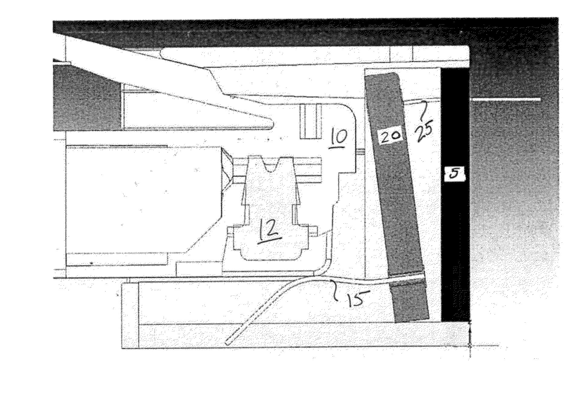
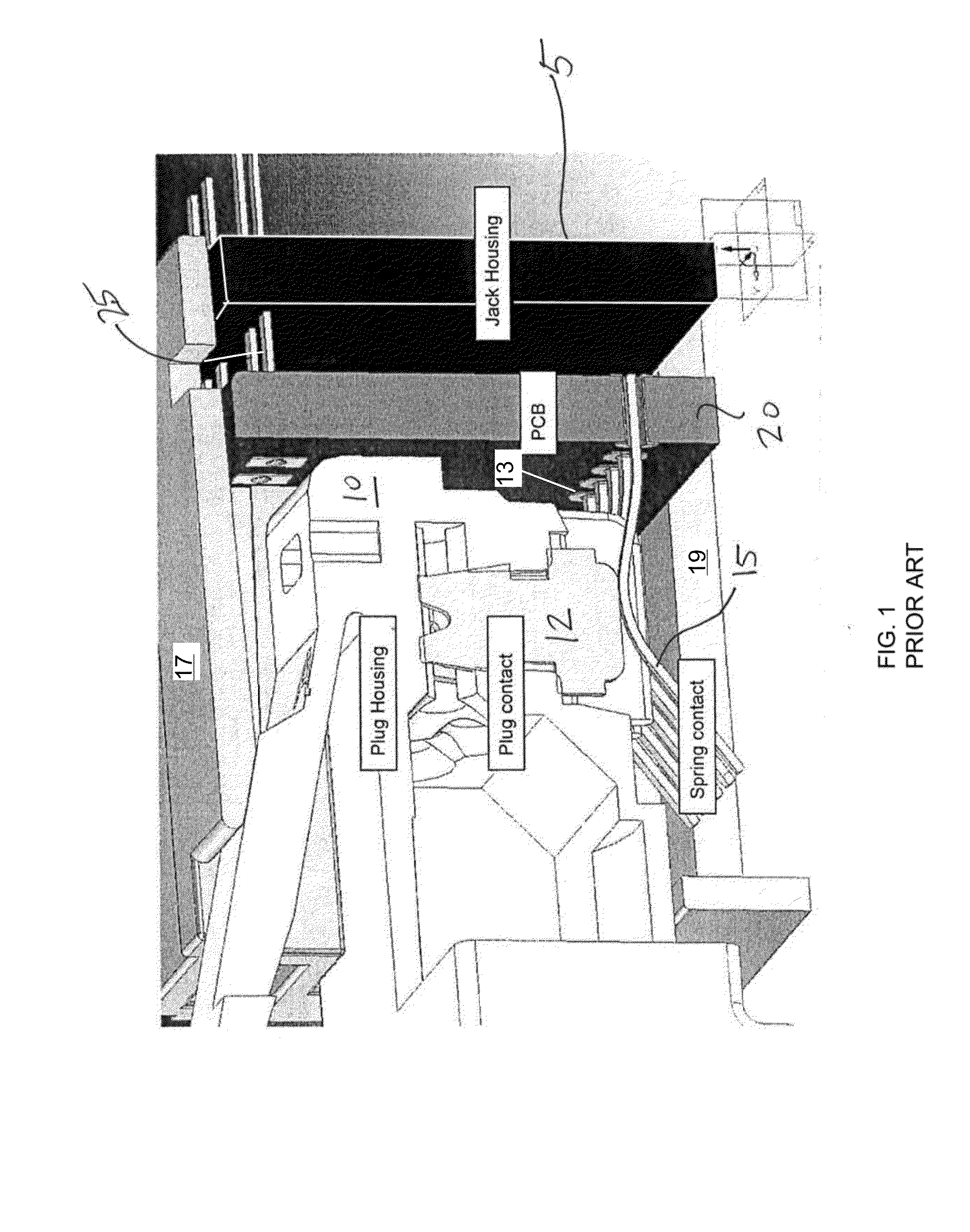
[0018]The following features are set forth in more detail in the detailed. description below:[0019](i) A female jack connector (5) utilizing electrical contacts (15);[0020](ii) Electrical contacts (15) in the female connector jack (5) relying on a flexible beam construction (i.e., a spring) for contact force;[0021](iii) A printed circuit board (PCB) or other mounting for the spring contacts (15) including compensation elements (30, 35, 40);[0022](iv) The printed circuit board (20) being allowed to move to absorb force and deflection of the spring contacts (15);[0023](v) A secondary spring (35) or support (40) for the printed circuit board (30) that provides resistance to movement of the printed circuit board (30), but allows movement of the printed circuit board (30) such that the spring contacts (15) are not overstressed.

[0024]Optionally, the design disclosed herein may also include:[0025](vi) A secondary spring may be in the form of output contacts (25) for electrical signals;[002...


PUM


Abstract

A jack assembly includes a top face and a bottom face defining a cavity there between for receiving a plug. The jack assembly includes a printed circuit board extending between the top and bottom faces of the jack assembly. At least one spring contact is connected to the printed circuit board and extends into the cavity. The spring contact defines a flexible curvature along a length of the spring contact, and the printed circuit board connects to the jack assembly at a pivot point allowing for angular rotation of the printed circuit board within the cavity. The angular rotation allows the jack assembly to absorb stress forces on the spring contacts. Secondary springs may be included in the jack assembly to further absorb spring contact stress forces.

Description

CROSS REFERENCE TO RELATED APPLICATIONS[0001]This non-provisional patent application claims priority to and incorporates entirely by reference U.S. Provisional Patent Application Ser. No. 61 / 794,363 filed on Mar. 15, 2013, and entitled “Spring Contact for Modular Connectors”.TECHNICAL FIELD[0002]This disclosure relates to a spring contact design for high frequency modular connectors such as plugs that fit into jacks for telecommunications signal transmission.BACKGROUND[0003]Jack housings utilizing spring contacts encounter consistent stress on the spring contacts due to repetitive use and due to users accidentally inserting plugs of the wrong size into the jack. A need exists in the art of plug and jack housings for mechanisms within the jack to lower the stress on spring contacts and to ensure contact integrity in the event that an improper plug is inserted therein.[0004]Without limiting the invention disclosed herein, the art of jacks and plugs has struggled with designing spring ...

Claims


Application Information

Patent Timeline
IPC IPC(8): H01R13/33
CPCH01R13/33H01R13/6466H01R24/64H01R2201/04
Inventor VADEN, STERLING A.
Owner OPTICAL CABLE CORPORATION
Why Eureka
Try Eureka