

Needle placement manipulator with attachment for rf-coil
a technology of needle placement manipulator and rf coil, which is applied in the field of medical devices, can solve the problems of long trial and error routine, damage to the patient, and the effect of the manipulator being jeopardized
- Summary
- Abstract
- Description
- Claims
- Application Information
AI Technical Summary
Benefits of technology
Problems solved by technology
Method used
Image

Examples
first embodiment
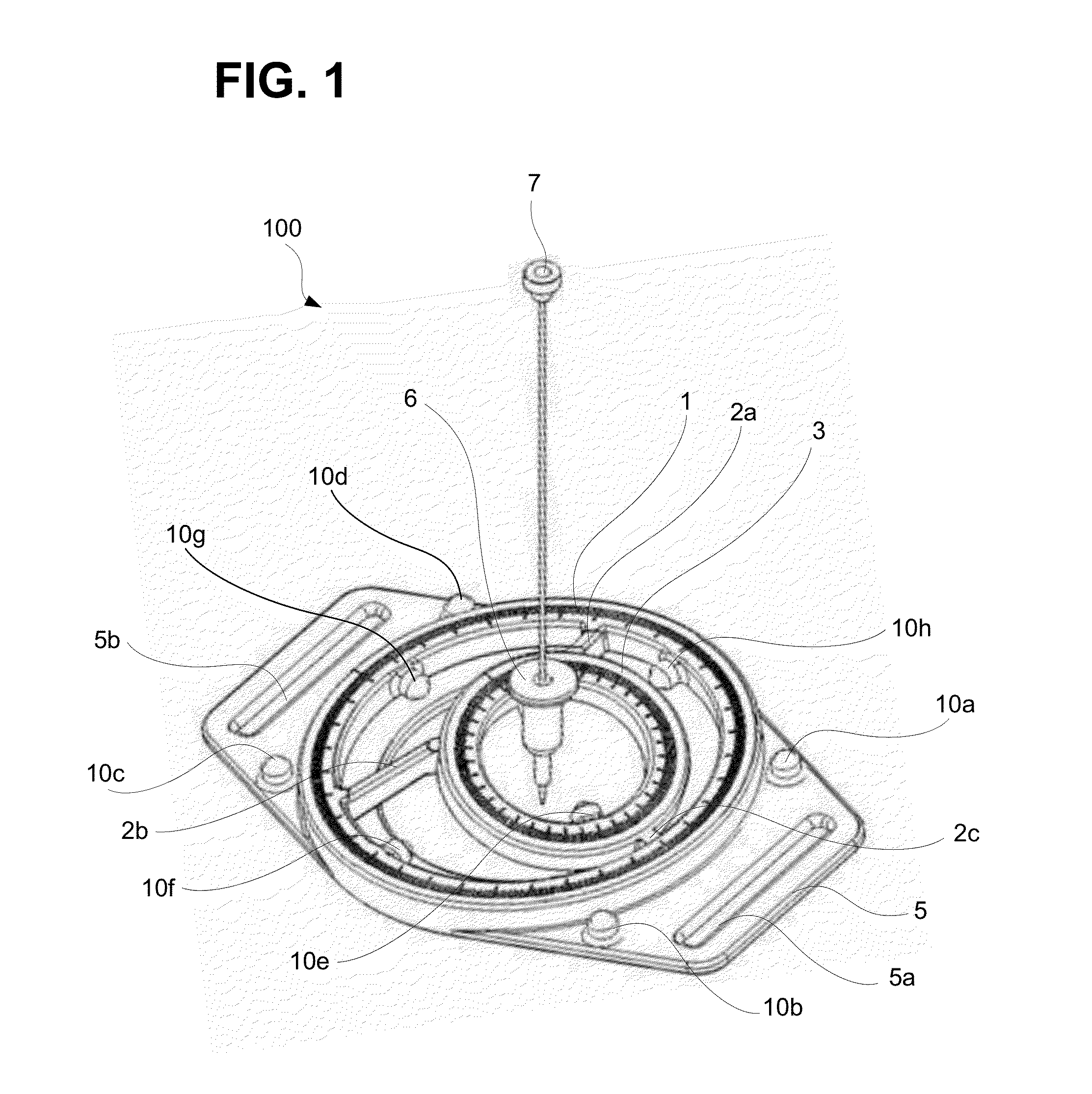
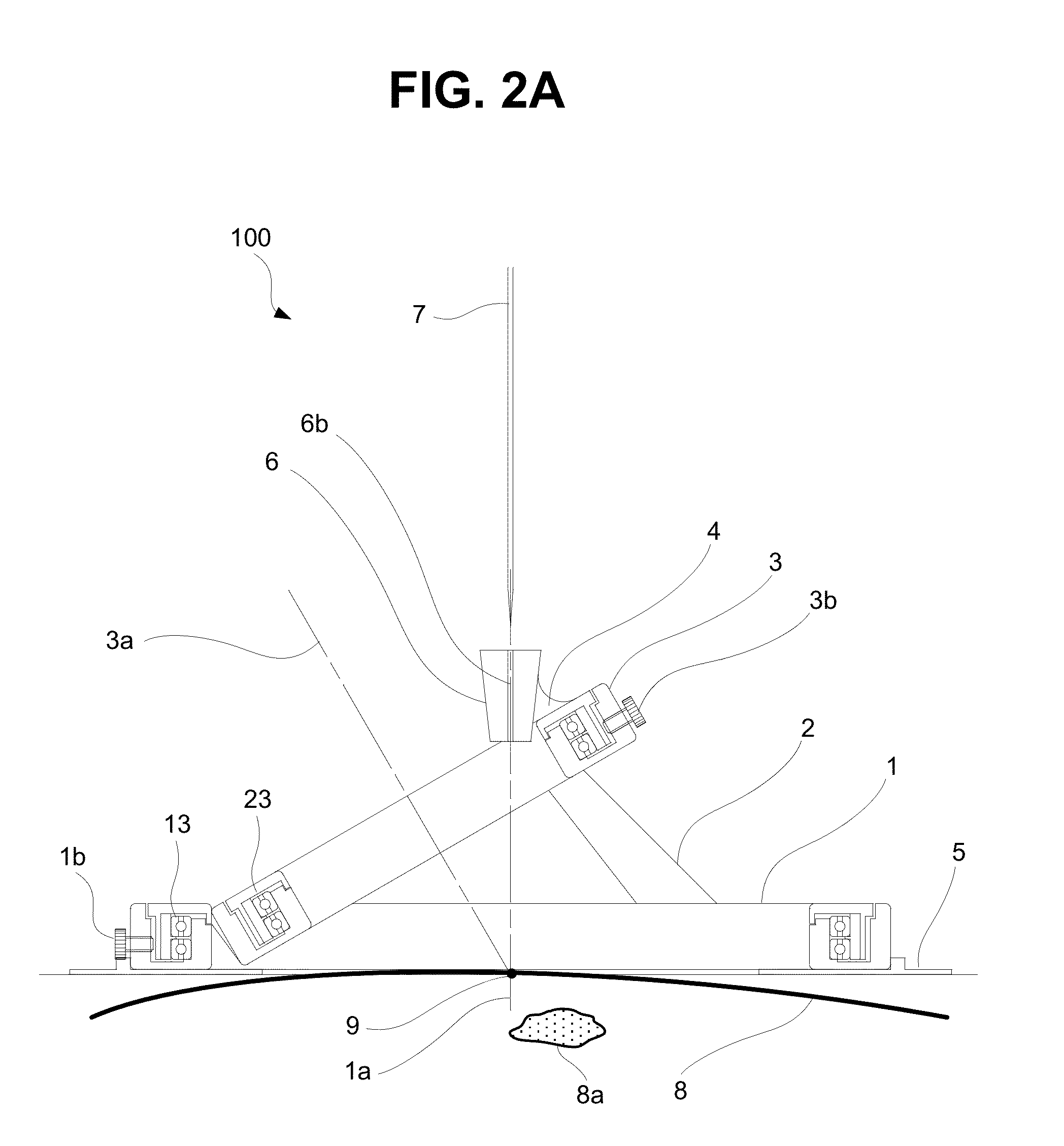
[0036]The first embodiment of the present invention is directed to a solution for the issues mentioned above. FIG. 1 is a perspective view of a needle placement manipulator 100 in accordance with the first embodiment. FIGS. 2A and 2B are sectional views of the needle placement manipulator at different operating positions.
[0037]As illustrated in FIG. 1, according to the first embodiment, a needle placement manipulator 100 includes two circular ring-shaped rotary guides (hereinafter referred simply to as “rotary guides”), which are arranged in a slanted orientation with respect to each other atop a base body 5. Specifically, a first rotary guide 1 and a second rotary guide 3 are arranged in a slanted orientation with respect to each other. The two rotary guides 1 and 3 are supported by a base body 5. The base body 5 is preferably a non-magnetic structure configured to be mounted on a patient's skin 8. As discussed in more detail below, the base body 5 and certain other elements can be...
second embodiment
[0055]FIGS. 5A and 5B are sectional views of a needle placement manipulator 200, in accordance with a second embodiment. FIG. 6 is a detailed sectional view of the left side of FIG. 5A. The second embodiment is substantially similar to the first embodiment. One notable difference in the needle placement manipulator 200, according to the second embodiment, is that the manipulator 200 includes motorized actuators for the rotation of first and second rotary guides 1 and 3.
[0056]Specifically, in this embodiment, the first rotary guide 1 now includes a rotation drive unit 210, and the second rotary guide 2 includes a rotation drive unit 220. In the first rotary guide 1, the rotation drive unit 210 comprises a piezoelectric actuator 11, a rotary slider 12, a ball-bearing 13, a screw part 14, a pressurized means 15, a first electric cable 16, a position sensor 17, a rotary scale 18, a second electric cable 19, and an external casing 1.1 and internal casing 1.2.
[0057]As shown in FIG. 6A, th...
third embodiment
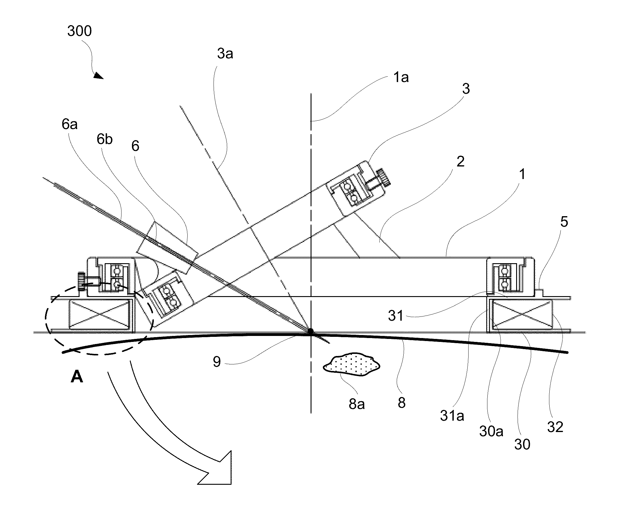
[0075]A third embodiment is now described with respect to FIGS. 8A, 8B and 9. A needle manipulator 300, in accordance with the third embodiment is substantially similar to the manipulator 100 of the first embodiment in that needle positioning is effected by manually rotating the rotary guides 1 and 3. A notable difference in the third embodiment, in contrast to the first one, is that the manipulator 300 includes an attached RF-coil.
[0076]Specifically, FIG. 8A is a perspective view of manipulator 300 and FIG. 8B is a perspective view of the manipulator 300 showing a vertical cut along plane H-H, in accordance with third embodiment. FIG. 9A is a sectional view of the manipulator 300 cut along the vertical plane H-H, according to the third embodiment. The needle manipulator 300 of the present embodiment may be particularly suitable for use in MRI-guided percutaneous interventions. In this embodiment, the manipulator 300 includes attachments for an RF-coil which is used in a MRI-scanner...
PUM
 Abstract
Description
Claims
Application Information