
System for surgical information and feedback display

Active Publication Date: 2014-09-18
ORTHOSENSOR
View PDF3 Cites 26 Cited by
  • Summary
  • Abstract
  • Description
  • Claims
  • Application Information

AI Technical Summary

Benefits of technology

The patent is about a new method for aligning medical devices on a patient's body during surgical procedures. The current process of trial and error can result in poor outcomes and high costs. The invention aims to provide a simpler and more efficient way to align implants and reduce medical costs. The patent describes a system that uses sensors and software to accurately align devices on a patient's body and improve the accuracy of surgical procedures. The technical effects of this invention include improved functional efficacy, patient comfort, and longevity of the prosthesis.

Problems solved by technology

Orthopedic alignment currently involves cycles of trial and error.
Even with mechanical jigs, trialing, and advanced prosthetic components, outcomes including functional efficacy, patient comfort, and longevity of the prosthesis may not always be highly predictable, especially if procedures are performed by physicians and surgeons with different levels of skill, experience, and frequency of repeating an individual procedure.
Accurately determining and aligning an implant orientation is a difficult process requiring expensive equipment.

Method used


Image

  • System for surgical information and feedback display
  • System for surgical information and feedback display
  • System for surgical information and feedback display

Examples


Embodiment Construction

[0080]The following description of embodiment(s) is merely illustrative in nature and is in no way intended to limit the invention, its application, or uses.

[0081]For simplicity and clarity of the illustration(s), elements in the figures are not necessarily to scale, are only schematic and are non-limiting, and the same reference numbers in different figures denote the same elements, unless stated otherwise. Additionally, descriptions and details of well-known steps and elements are omitted for simplicity of the description. Notice that once an item is defined in one figure, it may not be discussed or further defined in the following figures.

[0082]It will be appreciated by those skilled in the art that the words “during”, “while”, and “when” as used herein relating to circuit operation are not exact terms that mean an action takes place instantly upon an initiating action but that there may be some small but reasonable delay, such as a propagation delay, between the reaction that is...


PUM


Abstract

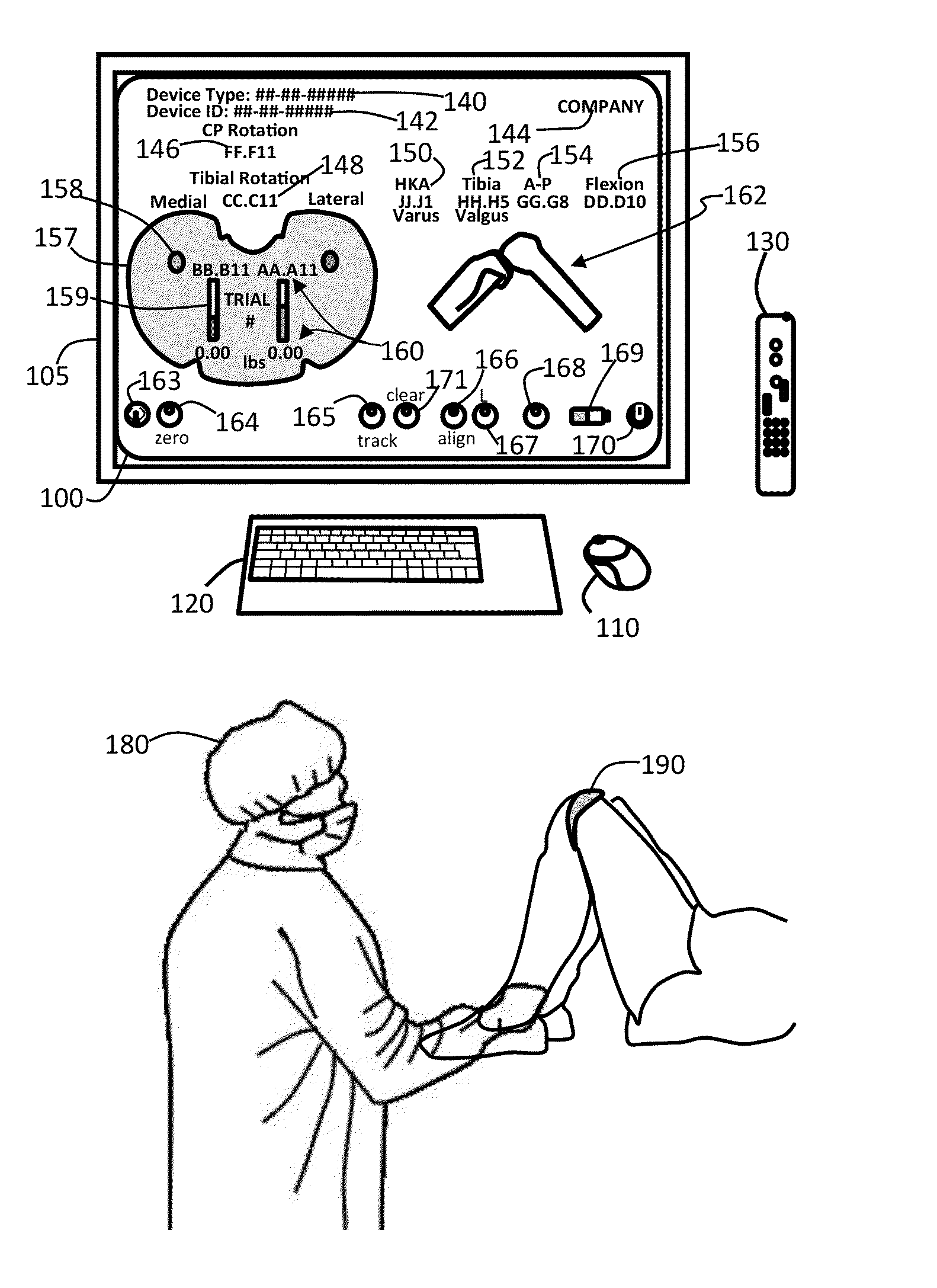
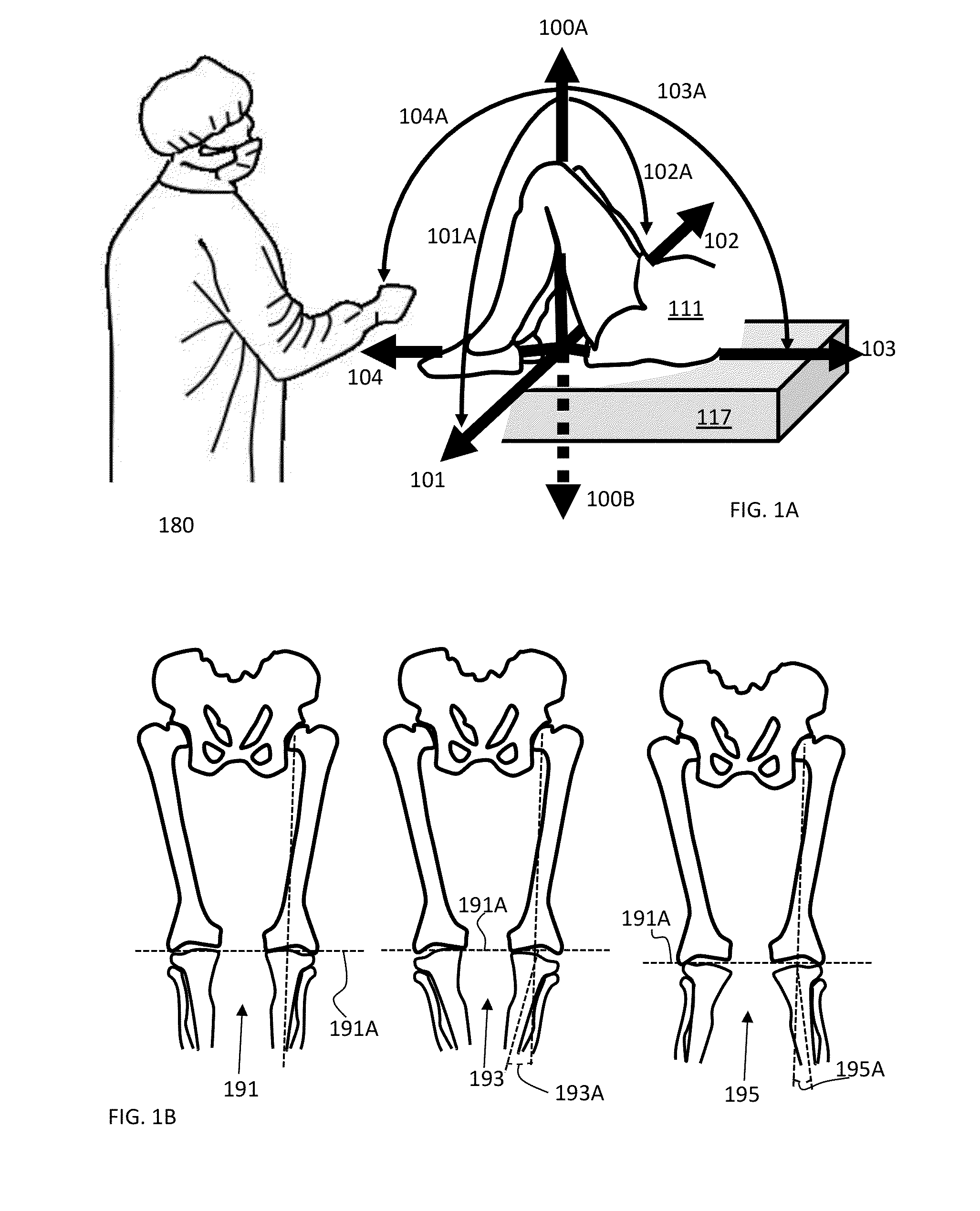
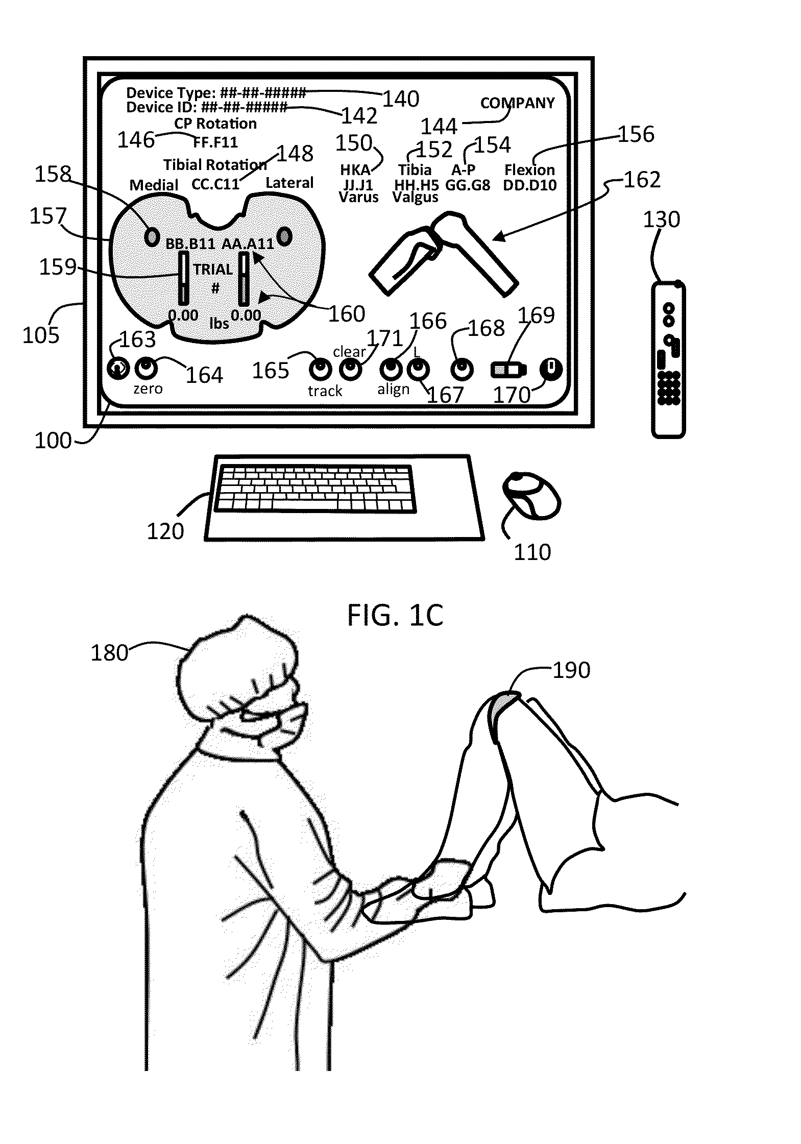
A graphical user interface having a portion of an orthopedic system displayed on an electronic display. Where the graphical user interface displays: a parameter of the orthopedic system; a portion of an orthopedic insert; and a parameter of the orthopedic insert. Where in response to detecting movement of the orthopedic system the displayed portion of the orthopedic system is moved, a change of the parameter of the orthopedic system is displayed, and a change in parameter of the orthopedic insert is displayed.

Description

CROSS-REFERENCE TO RELATED APPLICATIONS[0001]This application claims the benefit of U.S. provisional patent application No. 61 / 803,078 filed 18 Mar. 2013. The disclosure of which is incorporated herein by reference in its entirety.FIELD OF THE INVENTION[0002]The invention relates in general to medical and surgical procedures and more particularly to aligning medical devices to precise locations on or within a patient's body.BACKGROUND OF THE INVENTION[0003]Orthopedic alignment currently involves cycles of trial and error. For example, leg alignment requires a technique that approximates alignment in which the surgeon makes one of the distal femoral cut and the proximal tibial cut based on experience, mechanical jigs, and visual alignment. Typically, the proximal tibial cut is made so as to remove the least amount of the proximal tibia, while ensuring sufficient removal of diseased or otherwise undesirable bone. The remaining femoral cuts are made to complete shaping of the femur to ...

Claims


Application Information

Patent Timeline
IPC IPC(8): A61F2/46A61B19/00
CPCA61F2/4657A61F2/461A61B19/5225A61B5/1072A61B5/4571A61B5/4585A61B5/4887A61F2/38A61F2/4684A61B17/155A61B17/157A61B2034/104A61B5/1036A61B34/20A61B90/37A61B5/1121A61B5/4528A61B5/4851A61B5/686A61B17/154A61B34/25A61F2002/4668A61F2002/4658A61B5/45A61B5/103A61B17/1764A61F2/3836A61B34/10A61B2034/102A61B2034/105G06F3/0481
Inventor STEIN, MARCROCHE, MARTIN
Owner ORTHOSENSOR
Learn More