Tri-fluted vascular access needle

a vascular access and tri-fluted technology, applied in the field of medical needles, can solve the problems of significant cumulative damage, several complications, and the maintenance and longevity of vascular access remains one of the most problematic topics

Active Publication Date: 2014-09-18
COOK MEDICAL TECH LLC
View PDF8 Cites 50 Cited by
  • Summary
  • Abstract
  • Description
  • Claims
  • Application Information

AI Technical Summary

Problems solved by technology

For treatment personnel (e.g., surgeons and those assisting them), choosing the best site for an initial puncture and the best path for the introduction of devices poses a challenge for any endovascular procedure.
For example, the maintenance and longevity of vascular access remains one of the most problematic topics in the care of dialysis patients.
Although much attention has focused on neointimal hyperplasia, the repetitive trauma to vessel walls by dialysis needles causes significant cumulative dama...

Method used


Image

  • Tri-fluted vascular access needle
  • Tri-fluted vascular access needle
  • Tri-fluted vascular access needle

Examples


embodiment 200

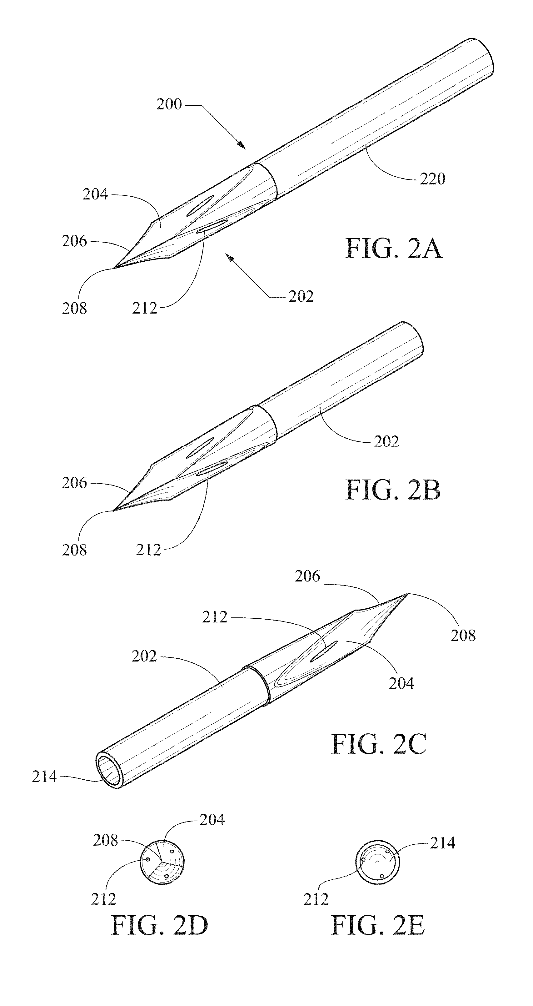
[0021]A second needle embodiment 200 is shown in FIGS. 2A-2E. FIG. 2A shows the distal end portion of the tri-fluted needle 200 with a cannula 220 extending proximally from the needle body 202. FIGS. 2B-2E show the distal needle body 202 without the cannula 220. FIG. 2B shows the same perspective view as FIG. 2A, except without the cannula 220 overlying and extending proximally from a base portion of the distal needle body 202. FIG. 2C shows an opposite side view from FIGS. 2A-2B. FIG. 2D shows a distal-end elevation view including all three flutes 204 and ports 212, and FIG. 2E shows a proximal-end-view, of the distal body 202, including the lumen 214. The distal-end view of FIG. 2D shows that the cutting edges are oriented at about 120° relative to each other around the circumference of the cylindrical needle body 202.

[0022]The distal body 202 includes three longitudinal fluted surfaces 204, the adjoining borders of which form three longitudinal beveled cutting edges 206. The thre...

embodiment 300

[0023]A third needle embodiment 300 is shown in FIGS. 3A-3D. FIG. 3A shows the distal end portion of the tri-fluted needle 300 with a cannula 320 extending proximally from the needle body 302. FIGS. 3B-3D show the distal needle body 302 without the cannula 320. FIG. 3B shows the same perspective view as FIG. 3A, except without the cannula 320 overlying and extending proximally from a base portion of the distal needle body 302. FIG. 3C shows a distal end elevation view, and FIG. 3D shows a proximal end-view, of the distal body 302.

[0024]The distal body 302 includes three longitudinal fluted surfaces 304, the adjoining borders of which form three longitudinal beveled cutting edges 306. The three longitudinal fluted surfaces 304 and the three longitudinal beveled cutting edges 306 converge at a distal end terminus 308 to form a sharp point, which is congruent with the central longitudinal axis. The body 302 may include a plurality of semicircular-section ports 312, with one disposed in...

embodiment 400

[0025]A fourth needle embodiment 400 is shown in FIG. 4. FIG. 4 shows the distal end portion of the tri-fluted needle 400 with a cannula 420 extending proximally from the needle body 402. The distal body 402 includes three longitudinal fluted surfaces 404, the adjoining borders of which form three longitudinal beveled cutting edges 406. The three longitudinal fluted surfaces 404 and the three longitudinal beveled cutting edges 406 converge at a distal end terminus 408 to form a sharp point, which is congruent with the central longitudinal axis. The body 402 may include a wire guide port 414 proximal of the tapering distal end that includes the flutes 404 and edges 406. The wire guide port 414 provides communication with a longitudinal wire guide lumen 414 extending through the body 402 and cannula 420. This structure will allow the needle 400 to be used for providing access for a wire guide, and / or for the needle 400 to be directed along a wire guide.

[0026]Needle construction, inclu...


PUM


Abstract

A needle disclosed herein may include an elongate body extending between a proximal end and a distal end with a central longitudinal axis defined by the body, where the distal end includes a single sharp point along the central longitudinal axis and defining a distal end terminus three longitudinal fluted surfaces converging at the distal end terminus; and three longitudinal beveled cutting edges defining borders between the fluted surfaces and converging at the distal end terminus. Needle embodiments may include one or more ports open into and/or proximal of the fluted surfaces and communicating with one or more longitudinal needle lumens.

Description

CROSS-REFERENCE TO RELATED APPLICATIONS[0001]This application is a non-provisional application which claims priority to U.S. provisional application Ser. No. 61 / 782,572, filed Mar. 14, 2013, which is incorporated by reference herein in its entirety.TECHNICAL FIELD[0002]Embodiments disclosed herein generally relate to medical needles. More particularly the embodiments disclosed relate to vascular access needles.BACKGROUND[0003]Minimally invasive treatments including endovascular therapies are increasing preferred and used instead of traditional “open surgical” interventions whenever possible. Endovascular techniques may be used to diagnose and / or treat a broad range of pathologies. Therapies may range from critical limb ischemia and aneurysm repair to ischemic stroke therapies and treatment of vascular stenoses. All endovascular techniques require a vascular access site for device introduction into a vascular lumen. For treatment personnel (e.g., surgeons and those assisting them), c...

Claims


Application Information

Patent Timeline
IPC IPC(8): A61B17/34
CPCA61B17/3403A61B17/3417A61M25/06A61B2017/3454
Inventor HASELBY, KENNETH A.SHERMAN, SARA M.BAXTER, CHARLESHADLEY, RICHARDMILNER, KEITH
Owner COOK MEDICAL TECH LLC
Why Eureka
Try Eureka