Supercharge Your Innovation With Domain-Expert AI Agents!

Smart hot plug retaining mechanism and method

a technology of hot plugs and retaining mechanisms, applied in the field of electrical devices, can solve problems such as no advance notice of the removal of computer modules

Active Publication Date: 2014-09-25
AVAGO TECH INT SALES PTE LTD
View PDF3 Cites 2 Cited by
  • Summary
  • Abstract
  • Description
  • Claims
  • Application Information

AI Technical Summary

Benefits of technology

The patent is about a computer system that has a removable computer module. The module is secured in the computer system and has a protective device to prevent access to the securing mechanism. To remove the module, the protective device must be moved. When the protective device is moved, the computer system sends a signal to disable the module's functions and allow safe removal without shutting down the computer system. The technical effect of this invention is to enable safe and easy removal of the computer module without shutting down the computer system.

Problems solved by technology

Unfortunately, there is often limited to no advance notice that a computer module is being removed.

Method used


Image

  • Smart hot plug retaining mechanism and method
  • Smart hot plug retaining mechanism and method
  • Smart hot plug retaining mechanism and method

Examples


Embodiment Construction

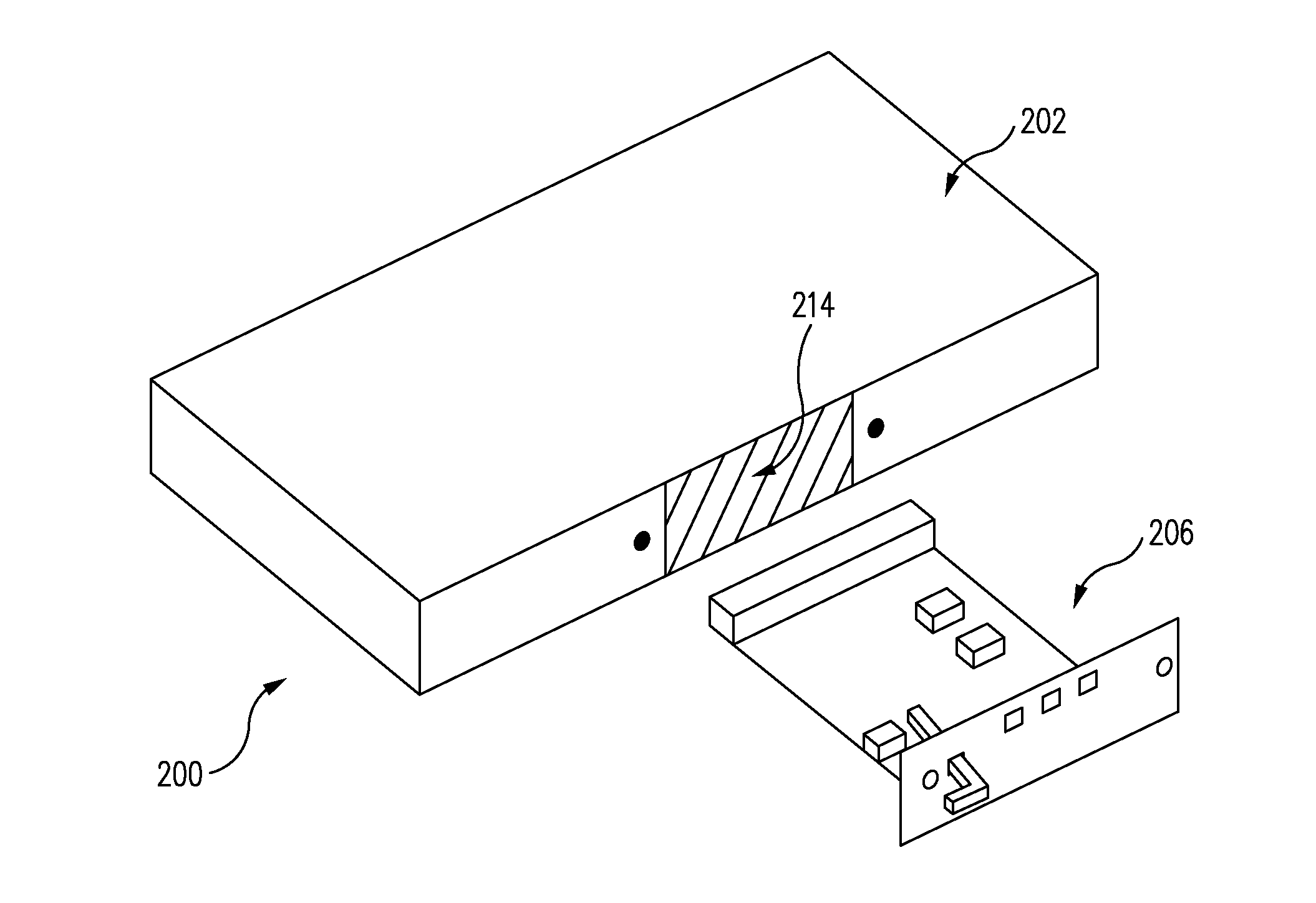
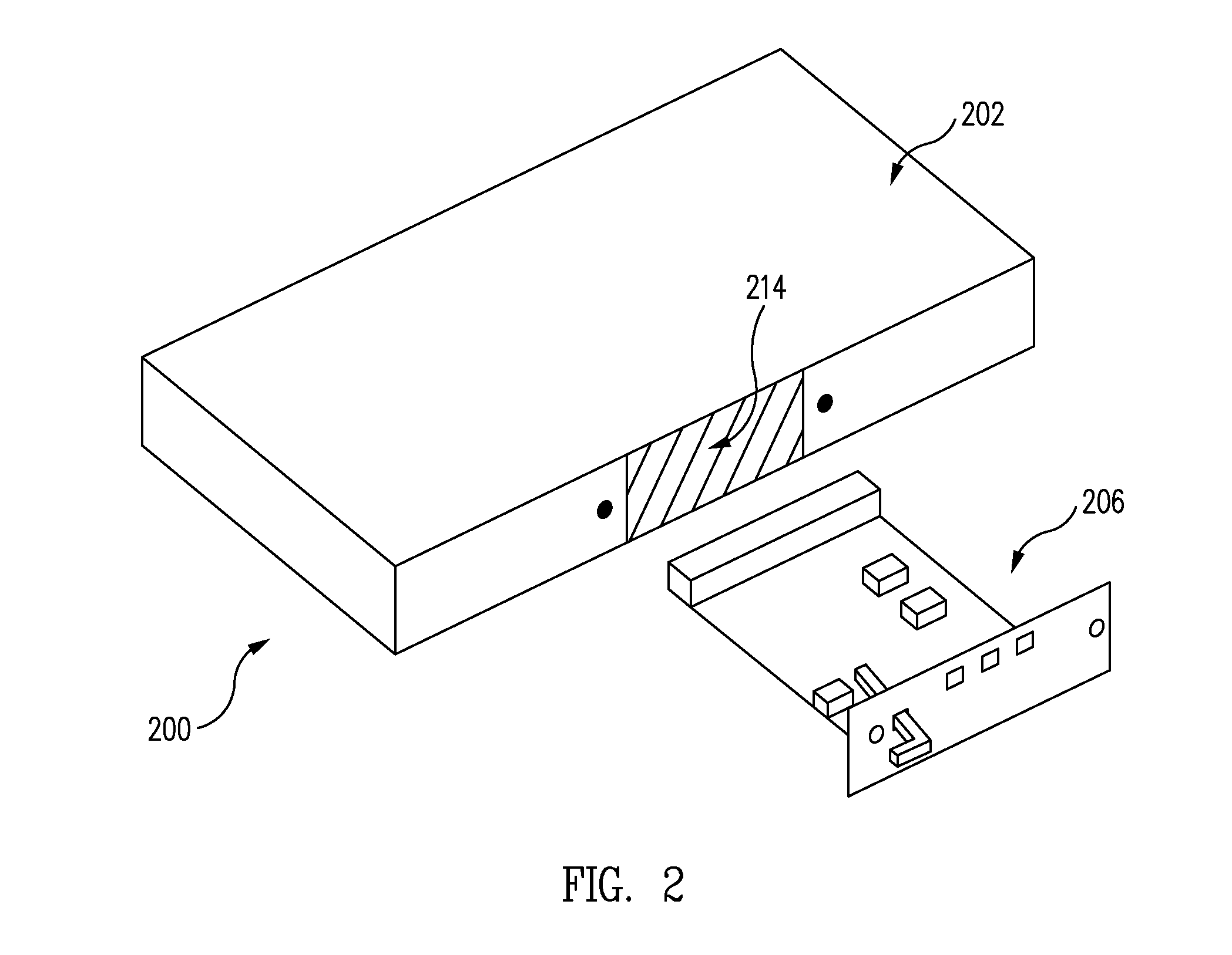
[0021]As an overview and in accordance with one embodiment, referring to FIGS. 2 and 5 together, a computer system 200 includes a removable computer module 206. Computer module 206 includes a retaining mechanism 308 securing computer module 206 within a computer system chassis 202 of computer system 200. Computer module 206 further includes a retaining mechanism protection device 310 preventing access to retaining mechanism 308 as illustrated in FIG. 5.

[0022]To remove computer module 206 from computer system chassis 202, a user must move retaining mechanism protection device 310 to gain access to retaining mechanism 308 as illustrated in FIG. 4. Upon notification of movement of retaining mechanism protection device 310, the central processing unit (CPU) of computer system 200 takes the appropriate operations to disable the functionality of computer module 206 and allow safe removal thereof without powering down computer system 200.

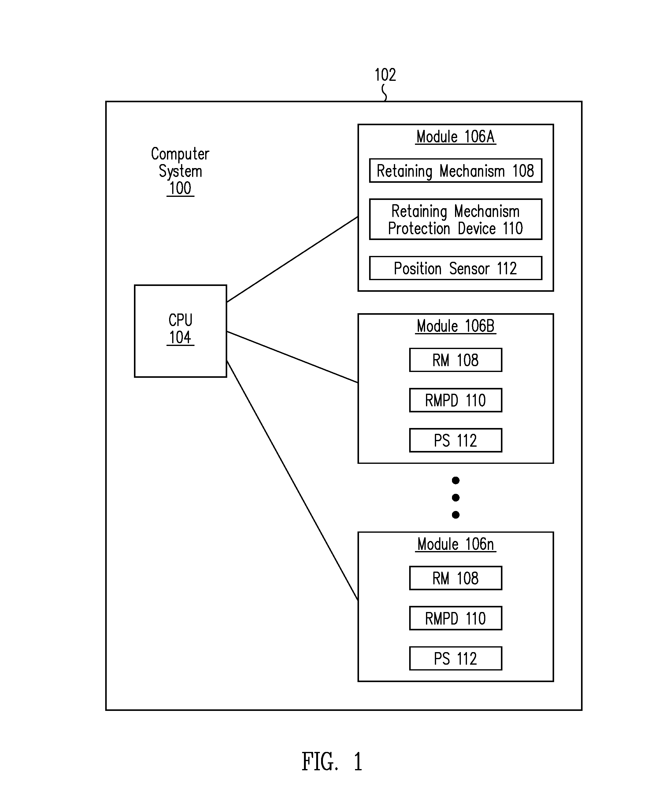
[0023]Now in more detail, FIG. 1 is a block diagram ...


PUM

PropertyMeasurementUnit
structureaaaaaaaaaa
timeaaaaaaaaaa
forceaaaaaaaaaa

Abstract

A computer system includes a removable computer module. The computer module includes a retaining mechanism securing the computer module within a computer system chassis of the computer system. The computer module further includes a retaining mechanism protection device preventing access to the retaining mechanism. To remove the computer module from the computer system chassis, a user must move the retaining mechanism protection device. Upon notification of movement of the retaining mechanism protection device, the CPU takes the appropriate operations to disable the functionality of the computer module and allow safe removal thereof without powering down the computer system.

Description

RELATED APPLICATIONS[0001]This application claims the benefit of U.S. Provisional Application No. 61 / 804,549 filed on Mar. 22, 2013, entitled “Smart Hot-plug Latch and Protection Method” of Michael Lee, which is incorporated herein by reference in its entirety.BACKGROUND[0002]1. Field[0003]The present application relates to the field of electronics, and more particularly, to structures and methods for securing modules within a computer system chassis.[0004]2. Description of the Related Art[0005]Computer systems are formed with computer modules, which support various functionality of the computer system. To allow easy repair, upgrade, or other access to the computer modules, computer system chassis are formed with computer module bays into which the computer modules can quickly be inserted and removed.[0006]Traditionally, removal of a computer module involved powering down the computer system, removing and / or replacing the computer module, and then powering the computer system back u...

Claims


Application Information

Patent Timeline
Patent Type & Authority Applications(United States)
IPC IPC(8): G06F1/18
CPCG06F1/183Y10T29/49004Y10T29/49826
Inventor LEE, MICHAEL K. T.
Owner AVAGO TECH INT SALES PTE LTD
Features
  • R&D
  • Intellectual Property
  • Life Sciences
  • Materials
  • Tech Scout
  • Unparalleled Data Quality
  • Higher Quality Content
  • 60% Fewer Hallucinations
Learn More