Method for perishable food or item in a container with a container storage technology

Inactive Publication Date: 2014-09-25
MELCHER JEFFREY S
9 Cites 20 Cited by

AI-Extracted Technical Summary

Problems solved by technology

Product containers, packaging and container storage technologies impact product effectiveness, d...

Method used

[0153]Referring now to FIG. 11, another embodiment can include a flexible or deformable container cover which can include a cover, top or center or side piece (100) constructed of a deformable, flexible, semi-rigid or jointed material (101), or combinations thereof and can include an annular, semi-rigid center piece (102) formed and sized to cover or exceed the circumference of the aperture of a container. A cover can be constructed such that when threaded or pushed onto the neck or aperture of a container the annular flexible or deformable cover, top or center piece is positioned and aligned to cover and seal the aperture or mouth of said container and is secured into said position via the engagement of the cover and container threads. In this position, air is prevented from entering into said container and the container contents are closed and sealed therein. Further, a vacuum applied to a container in this position can ev...

Benefits of technology

[0006]Objectives of the invention include providing efficient and simpler to use food storage...

Abstract

A method and system for manufacturing, producing, preparing, packaging, displaying, selling and marketing perishable food or items in a container with a container storage technology for use with select consumer goods or household appliances. A method and system for the use of multiple brand logos or names and communicative indicia on a container or product packaging wherein at least one of the brand logos or names, such as a secondary or tertiary brand logo or name can be used to represent different or distinct products, services or benefits from the primary brand logo or name.

Application Domain

Lighting and heating apparatusMaterial analysis by electric/magnetic means +13

Technology Topic

Perishable foodEngineering

Image

  • Method for perishable food or item in a container with a container storage technology
  • Method for perishable food or item in a container with a container storage technology
  • Method for perishable food or item in a container with a container storage technology

Examples

  • Experimental program(1)

Example

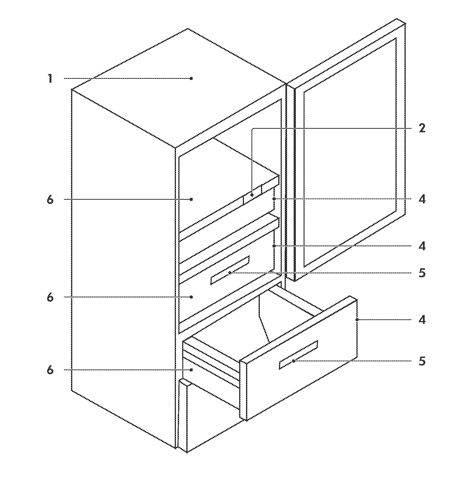
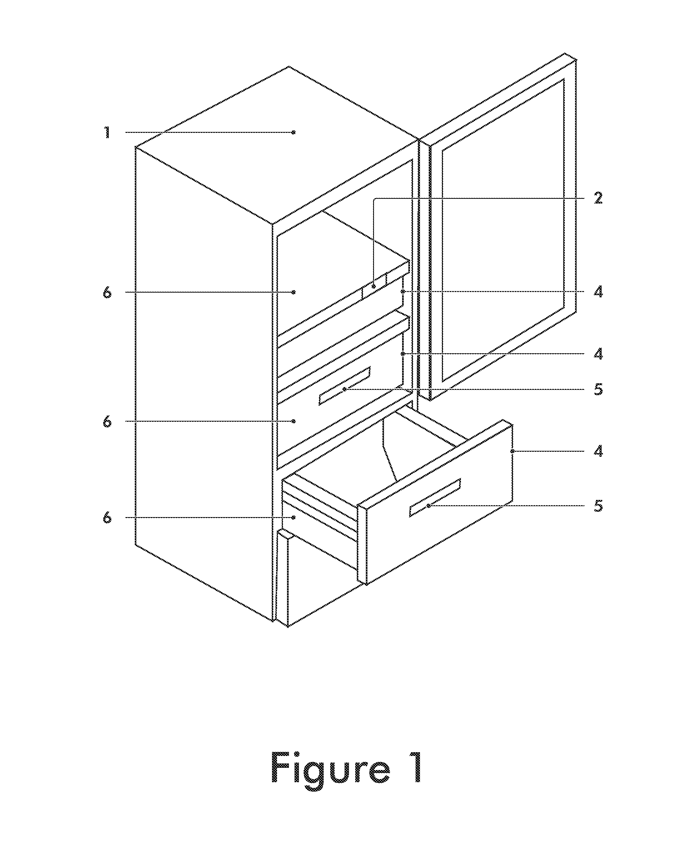
[0106]The invention will now be described with reference to the attached non-limiting Figures. In a preferred embodiment and as described herein, a vacuum storage system can comprise any of the following such as, a housing (1) shown in FIG. 1, in which at least one sealable modular compartment (6) can be disposed with at least one or more containers disposed therein. A compartment (6) can also be removably disposed inside a housing. Physically removed from and in communication with the interior of a compartment is a pump to create vacuum, pressure and other environments inside said compartment and containers disposed therein. A control system (2), which can include a display panel, microprocessor (CPU) and memory device, as well as, operating system controls, as shown in FIG. 4, can selectively or automatically activate and deactivate a pump and place said pump in either a vacuum or pressure mode or function. Further, said pump can function in a vacuum or pressure mode and can pump, vent or draw air into or out of an open or sealed compartment. Furthermore, a pump with a vacuum or pressure function can connect to the interior of a compartment and communicate with a control system, sensors and release valves connected and in communication with said compartment.
[0107]Another embodiment, as shown in FIG. 3, provides an apparatus housing (18) and operating systems to create, monitor, regulate, maintain and release compartment or container environments such as vacuum, pressure, temperature, humidity, venting and outgassing, all of which can connect to and communicate with a control system, each individual operating system, sensors and a compartment. Operating systems, as described herein, can include a pump(s) (89), sensors (50) (which can include humidity, gas, temperature, tactile, time and vacuum, and as described herein), valves (90), system status indicators and controls and temperature (40) and humidity (35) control devices (operating system(s), systems and components). A temperature system (40) can create a range of temperature inside a housing (18), a compartment (6) and a container (30) disposed therein and can connect to a control system (2) and to individual or selected system components. A humidity system (35) can create a range of humidity inside a compartment and a container disposed therein and can connect to a control system and to individual or selected system components. Furthermore, vacuum, temperature and humidity systems can connect to sensors and said sensors can connect to vacuum, temperature and humidity systems to activate, deactivate, interrupt, create, regulate and maintain individual or selected operating systems, processes and environments as described herein. For example, temperature, vacuum, gas and humidity sensors, can communicate with a control system and can individually or in combination activate or deactivate a pump or valve(s) to an open or close position when a predetermined level, range or value of temperature, vacuum, gas, time or humidity is created, maintained or exceeded inside a compartment or inside a container disposed therein or after a preset period of time. A compartment can include a seal (91) on the open and close mechanism or device for the compartment aperture.
[0108]Status indicators can include a light or series of lights located on the front of a drawer or compartment which illuminate in colors to inform of the system status, such as, red when a vacuum is being created and green when a vacuum is being released from a compartment.
[0109]As shown in FIGS. 1-2, a housing (1) can include a compartment (6) disposed therein comprising exterior walls with a slidable drawer (4) that can serve as an internal holding area or retaining compartment (9) for goods with a front wall (10) that can serve as a means to open, close or seal said compartment. Housings can include, but are not limited to, a refrigerator, freezer, cabinet, shell and drawer. A compartment can include an aperture comprising a drawer (6), door (93), bin, pivot bin, lid or cover, any of which can be hingedly attached to a housing or compartment or surrounding area.
[0110]As shown in FIGS. 2-3, a vacuum compartment (6) can be constructed and arranged so that when a retaining compartment, such as a drawer (10), is in a closed position inside a compartment said drawer can create a seal between the engaging surfaces of a compartment and the interior of a drawer. The created seal can also be airtight or can create a vacuum seal. Further, in other embodiments, when a vacuum is created inside a compartment a seal can be formed between a front wall of a drawer unit (7) and the walls of a compartment (8). A sealing device (91) can also be provided positioned between or around the engaging surfaces of a compartment and the interior (9) of a drawer or a door (93). Additionally, a sensor (12) can be positioned on a drawer or door of a refrigerator or compartment and connect to operating systems and to a control system to indicate the open, close and seal status to activate and deactivate individual or selected operating systems. Furthermore, a mechanical or electrical latch mechanism can be provided to secure a drawer and a compartment together when the interior portion of a drawer is substantially contained inside a compartment to engage a drawer and a compartment together to seal said compartment interior. A latch mechanism can connect to a control system and to individual or selected operating systems to activate or deactivate individual or selected operating systems. A drawer can also include a handle (5).
[0111]As shown in FIG. 4, other aspects of the invention provide a programmable control system, which can consist of a display panel (41), operating system controls (42) and a microprocessor and memory device (92), for a housing or a compartment to connect and communicate with operating system components to activate, deactivate, control, monitor, release and regulate a pump(s) (43), latch mechanism, sensors (50), valves (48), system status indicators connected to sensors, and controls, and vacuum, temperature and humidity systems. Accordingly, each operating system and compartment can interconnect and inter-communicate with each other, or via a control system, to function together or individually to carry out the processes described herein. Accordingly, a control system can activate or deactivate a pump to vent, cool or create vacuum and pressure environments inside a compartment, as well as, activate or deactivate a gas or release valve to open or close positions to seal or unseal a compartment. Additionally, a control system can connect to and communicate with sensors (50) described herein and said sensors can connect to and communicate with a control system (20) and each operating system such as a pump(s), valves, latch mechanism, sensors, system status indicators, system controls and vacuum, temperature and humidity systems to activate, deactivate, create, monitor, regulate, maintain and release environments, such as, vacuum, pressure, temperature, humidity, gas, air, components and processes for and in a housing, compartment and containers disposed therein and combinations thereof. A user interface with an led display and apparatus power source (46, 47) with touch, keyed or digital display panel functionality can operatively connect to and communicate with a control system to allow the input of instructions, formulas, time sequences and values to operate each or selected system components, systems and processes described herein. A user interface, situated on a compartment or a housing exterior or interior front panel, access or surrounding areas can also comprise touch panel controls, switches, buttons and knobs to connect to and communicate with operating systems and housing components. The operating systems can be programmed to be activated and deactivated automatically via a control system or manually via a control panel or via each operating system.
[0112]In another embodiment a vacuum sensor can communicate with a compartment interior and operatively connect to a housing, compartment or control system to open and close a gas or release valve and to activate and deactivate a pump(s). Alternately, a vacuum sensor can connect directly to a pump(s), a housing, compartment or valve. Furthermore, a housing or compartment sensor, as described herein, such as vacuum, temperature, pressure, tactile, drawer and refrigerator door open, close and seal status sensors can operatively connect in combination to a pump, valve(s), sensors and housing or compartment operating systems to open and close a valve(s) or to activate or deactivate a pump(s).
[0113]A control system or pump and valve can also be activated to vent or cool a compartment interior by activating a pump to draw or pump air through a compartment interior and contemporaneously activate a valve or a release valve to open positions. A housing or compartment control system or a vacuum sensor can activate a pump and a valve to create a predetermined vacuum level in a compartment or container disposed therein. A pressure release or valve can release a predetermined amount of vacuum from inside a compartment at a predetermined time period, pressure level or when a level is reached or exceeded and a vacuum can also be released via the aperture of a compartment.
[0114]As shown in FIG. 4, a compartment can comprise multiple storage functions or modes (45) such as, but not limited to, a conventional compartment with operating systems placed in either off or idle positions, a vacuum compartment, a pressurized compartment, a venting compartment, a cooling compartment, a humidity compartment, an outgassing compartment and a processing compartment to create environments inside containers disposed therein, such as temperature, humidity, vacuum, pressure, venting, cooling and outgassing.
[0115]Some of the apparatus, operating system and control system functionalities and modes can include, but are not limited to, the following. [0116] 1. A function to create a range of temperature inside a housing to cool a compartment or container disposed therein. [0117] 2. A function to activate a pump and close a valve or to close a valve and activate a pump or to contemporaneously activate a pump and close a valve to create a vacuum environment inside a compartment when said compartment aperture is closed and sealed. [0118] 3. A function to activate a pump and close a valve or to close a valve and activate a pump or to contemporaneously activate a pump and close a valve to create a pressurized environment inside a compartment when said compartment aperture is closed and sealed. [0119] 4. A function to activate a pump (in vacuum or pressure mode) while a compartment valve is contemporaneously actuated to an open position to vent, cool or degas said compartment and contents therein. Furthermore, a temperature sensor or control system can activate a valve to a close position after a predetermined value, time period or level of vacuum, temperature or humidity has been established, reached or exceeded inside a compartment. [0120] 5. A function to activate a pump (vacuum or pressure mode) and to simultaneously close a valve to create a pressure or vacuum environment inside a compartment and to maintain said pressure or vacuum level inside said compartment until it is deactivated manually or automatically via a control system. [0121] 6. A function to activate a pump and to close a valve to create a pre-determined vacuum in a compartment and when said maximum pressure level reaches or exceeds a pre-determined level, time period or value to then deactivate said pump and open a valve to release said vacuum and open said compartment by admitting air into said compartment. [0122] 7. A function to activate a pump and to close a valve to create a pre-set vacuum level inside a compartment and when said maximum vacuum level reaches or exceeds a pre-determined time period, level or value to open a valve to release said vacuum by admitting air into a compartment and to deactivate said pump. [0123] 8. A function to activate a pump and to close a valve to create a vacuum inside a compartment and when said maximum vacuum level reaches or exceeds a pre-determined level, time period or value to concurrently open a valve and deactivate a pump to admit air into said compartment to release said vacuum. [0124] 9. A function to activate a pump and to close valves to create a pre-set vacuum in a compartment and thereafter for a pump to intermittently remove air or gas from the interior of said compartment or a container disposed therein. Further, said pump can intermittently remove air and gas following the reduction of the pressure in a compartment to a selected pressure. Additionally, a gas sensor, such as an ethylene, oxygen, carbon dioxide or other gas sensor or as described herein, can connect to a compartment interior, a control system or operating systems such that when a predetermined air or gas(es) level(s) fail, reach or exceed a pre-determined level or value inside a compartment a sensor can communicate with a control system or activate a pump to remove additional air or gas from said compartment. Further, a sensor can communicate with a control system, activate a pump or activate a valve to an open position to remove additional air or gas from a compartment. A sensor can also activate a pump and activate a valve to an open position to vent a compartment and remove air or gas, including a container disposed therein. The aforementioned sensors can also be located inside a container and function as previously described. [0125] 10. A function to activate a pump and to close a valve to create a vacuum in a compartment, maintain said vacuum level for a pre-determined period of time and, thereafter, open a valve to admit air into said compartment to release a vacuum. [0126] 11. A function to activate and place a valve in a closed or open position to seal or unseal a compartment to create, regulate and release environments from inside a compartment. [0127] 12. A function to concurrently open a valve and to activate a pump (vacuum or pressure mode) to admit air into a compartment to release or create environments therein. [0128] 13. A function to deactivate a pump when a valve is in a close position to admit air into a compartment through an open and close aperture mechanism, such as a drawer or door opening, of a compartment to release a vacuum. [0129] 14. A function to deactivate a pump and admit air into a compartment through an open and close aperture mechanism, such as a drawer or door opening, of a compartment to release a vacuum. [0130] 15. A function to deactivate all or selected operating systems or place all or selected operating systems in an idle state. [0131] 16. A function to close or open a valve when a compartment aperture mechanism, such as a drawer or door opening, is in a close or open position via an aperture sensor placed on a compartment or refrigerator aperture and in communication with a control system. [0132] 17. A function that allows a valve to have an independent pressure setting or to be connected to a control system in a compartment to automatically open to release a vacuum created therein when a vacuum level is reached or exceeded inside said compartment and to automatically deactivate a vacuum pump creating said vacuum. As used herein, when a vacuum is released from a compartment said compartment is returned to atmospheric pressure.
[0133]Referring now to FIGS. 5 and 6, provided is a container to create multiple storage environments. A container can comprise any suitable material, such as plastic or glass or combinations thereof. A container can comprise a container body (51) with a sealable cover (52) that together can form an air-tight interior of a container (53). In the present embodiment, a cover can be fastened or attached to the container body in any manner (threads, fasteners, tongue and groove or a snap system) to engage and seal a cover and container body together to create and retain a vacuum or pressurized environment inside the interior of said container or to allow said container to vent.
[0134]A cover or container body can comprise two one-way valves, as shown in FIGS. 5 and 6. Valve (32) can allow air to enter (36) into a container and valve (33) can allow air to leave or exit (37) said container. A cover or container body can also comprise combinations of valves (32) and (36) and include a combination of openings and apertures (34) that open and close to allow air, gases or environments to be created inside and to enter and leave said container through either a one-way valve opening or via a container aperture. Valves and apertures can also include a rubber plug or stopper to seal said aperture and said container. In place of two separate valves, a three-way valve can be installed, which can be selected between one-way into the container, one-way out of the container, and both ways.
[0135]Each valve (32) and (36) and aperture (34) can be opened and closed by using said rubber plug or stopper (38) to prevent the flow of air, gases or environments into or out of said container. A sealing device can be a rubber plug or stopper device (38), or any other type of sealing mechanism, such as a toggle or switch that opens and closes the valves and apertures, a slidable cover, a dial, or any other closure system to seal and open said valve openings and apertures.
[0136]In this manner, the present container can be placed into a vacuum compartment wherein a vacuum is created inside said compartment and concurrently inside said container such that when a vacuum is released from the compartment the vacuum is concurrently released from the interior of said container if the proper valve(s) and apertures are open or the vacuum can be retained in the container if the proper valve(s) and apertures are closed.
[0137]Some of the following container environments can be created with said vacuum and container valve system when said container is placed inside a vacuum or pressure compartment. [0138] 1. When valve (32) is closed and valve (33) is open or valve (33) is open and aperture (34) is closed, a partial vacuum created inside a compartment is concurrently created inside said container and retained inside said container when the vacuum is released from said compartment. [0139] 2. When valve (32) is open and valve (33) is closed or valve (32) is open and aperture (34) is closed, a pressurized environment created inside said compartment is concurrently created inside said container and retained inside the container when the pressurized environment is released from said compartment. [0140] 3. When valve (32) is open and valve (34) is open or valve (33) is open and aperture (34) is open, a vacuum created inside said compartment is concurrently created inside the container. When a vacuum is released from the compartment it is also released from inside said container. When the compartment is outgassed said container is also outgassed. When additional gases or air are removed from said compartment the air and gases are also removed from said container. Further, when a pump is activated to draw air through the compartment, air is also drawn or vented through said container. This functionality can be used to vent respiring content such as fresh fruit, vegetables, etc., and to cool container contents. [0141] 4. Closing the valves on a container after a vacuum or a pressure environment is created inside a container prevents other environments from being created inside said container or from allowing existing container environments from releasing. Closing all the valves and apertures allows the container to be used as a conventionally sealed storage container.
[0142]The aforementioned environments 1-4, and others, can be sequenced into a valve or aperture open and closure position system and device, such as a dial, switch, toggle, twist or slide mechanism. For example, by turning a dial or moving a slide from one position to another a user can automatically create environment 1 and, thereafter, can sequentially create environments 2-4 by moving the valve and aperture covers into the proper positions. For example, a dial or slide can be moved to a fresh fruit or meat label or marker and automatically position the valves and apertures to the appropriate close and open positions to preserve said goods.
[0143]Each container can be constructed with temperature, non-conducive retractable, removable or collapsible legs so that when the containers are placed inside a compartment and a vacuum is created and maintained inside said compartment the vacuum insulates the container from the compartment surfaces thereby creating a thermos effect inside each container therein. Closed or open containers can be used. This effect can be used as a food or plate warming preservation type drawer system. Each container can also have temperature, non-conducive borders or tabs on a lid or container body to prevent contact with compartment surfaces or other containers placed inside said compartment. Cold and hot items can be simultaneously stored. Additionally, containers can be placed on top of a temperature, non-conducive mat or container holder positioned inside said compartment.
[0144]FIGS. 7-9 and 17 and 19 illustrate other embodiments of a cover and a container that can be used as a conventional storage container or as a vacuum sealing container. This embodiment includes a cover (70) (also; lid, top, cap) that detachably covers and seals an aperture (71) (also; mouth, opening) of a container (72) to allow a vacuum environment to be created therein. A cover can attach to a container by compression fit, thread attachment, snap or any other manner or combinations thereof. In this manner, a cover can close and seal a container in an airtight manner.
[0145]In the present embodiment, provided is a cover (70), comprising a thin, flat, annular (also: spherical, round, circular) sealing device (73) (seal), disposed and contained inside the interior of a cover. In one embodiment, a seal is contained in a cover by and between two extending, raised or protruding rings (74) that connect to and extend inwardly from the cover side walls or skirt. In another embodiment, a single ring (75) construction and arrangement can contain a seal. A cover can threadably (76) attach to a container. A cover can comprise a threaded interior neck (76) or aperture to threadably attach to a threaded exterior of a neck or aperture of a container (77) (or vise versa) or to another part of the cover that can be attached to said container. Depending upon the embodiment, the attachable threads of a cover and a container can engage to create an airtight seal or can engage without creating an airtight seal to allow air to pass through the threads. In other embodiments, engaging threads can be constructed and arranged to allow air into a container in a first position and then said engaging threads, when moved into a second position, can be arranged and constructed to create an airtight threading engagement to prevent air or a vacuum from entering or releasing from the interior of a container. Furthermore, a cover can include a sealable aperture or valve (78) to allow air into and out of the interior of the container via the cover and to create or release a vacuum from inside said container. FIG. 19 depicts a container with a flip top and seal located therein.
[0146]In one embodiment, a cover containing an internal seal can be disposed onto a receptacle and moved clockwise into a first position to arrange and align a seal onto or over the aperture of a container with the inside top or sides of the cover closing and securing said seal onto the aperture of the container to allow air to flow out of said container when a vacuum is applied to said container but restricting the movement of air into said container. In this position said internal seal covers and seals the aperture of a container and the contents therein. A vacuum can then be applied to said container when placed into a compartment to evacuate air from the interior of said container with said internal seal closing and sealing said container such that when the vacuum is released from inside said compartment the internal seal covering the aperture of the container is vacuum sealed closed creating a vacuum environment inside said container. A cover can then be moved counter clockwise into a second position to remove the seal from the top of the container aperture and simultaneously unseal and remove the seal from the aperture of the container releasing an airtight seal between the internal seal and the container thereby releasing the vacuum environment from the interior of said container.
[0147]In another embodiment, a cover can be disposed onto a receptacle and moved clockwise into a first position to arrange and align a seal onto or over the aperture of a container to allow air to flow out of said container but restrict the movement of air into said container and also attach said cover onto a container. In this position a seal covers the aperture of a container. A cover can then be moved clockwise into a second position to secure or lock said seal onto and over the top or opening of the aperture of a container creating an airtight seal so that air or a vacuum environment cannot enter or release from the interior of said container. A cover can then be moved counter clockwise into a third position to remove said seal from the top of a container aperture and simultaneously unseal and remove the seal from the aperture of the container thereby releasing an airtight seal between the seal and the container and to release the vacuum environment from the interior of said container. A fourth counter clockwise position can detach and remove said cover and seal from the aperture of said container. The cover and container can be devised to function and engage in a clockwise or counter clockwise manner and can include the functionality of push or compression fit cover to engage in the various steps described herein or in combinations thereof.
[0148]Continuing, the top interior walls or skirt of a cover can comprise a means to support, hold or contain a seal, such as raised, extending or protruding single or double rings, edges or lines, knobs or any other support or constraining type device mechanism (79) (rings) connected to the walls of the cover and extending inward away from the cover walls and constructed to hold a seal within a predetermined space and defined alignment. As shown in FIG. 9, a seal (73) can be sized and shaped with a circumference to cover and seal the aperture of a container and to contact the rings such that when a seal is positioned over and covering a container aperture said aperture is covered by said seal and can extend beyond the container aperture limits or edges to make contact with the rings extending from a cover. A seal can be constructed to move or float between two rings or between one ring and the top of a cover. In other embodiments, a seal can attach to the top or side walls of a cover to move or float and to align and cover the aperture of a container when a cover is attached to a container. A seal and top interior of a cover can be constructed such that a seal does not adhere or stick to the top of a cover. For example, the top of a cover can comprise a convex, raised or protruding ring, edge or line (74) extending downward and away from the top of a cover to prevent a seal from coming into contact and adhering to the top of a cover while also serving as a mechanism to secure and lock a seal onto the aperture of a container.
[0149]Another embodiment, as shown in FIG. 10, provides a cover (81) with a hollow circular skirt (82) constructed inside a cover skirt and attached to and extending downward from the interior top of a cover with a seal (73) contained inside said circular skirt and contained by a ring device (75), as previously discussed, to allow a seal (73) to float between the ring and the top (76) of a cover. When a cover is threaded (78) or pushed onto a container (79) into a first position the container aperture is constructed to fit into the hollow circular skirt to align and position a seal on top of a container aperture. In this position, a container aperture is covered by a seal and air can be evacuated from the interior of a container to create a vacuum environment therein. In other embodiments, a cover and container engaging threads (80) are constructed and arranged to allow air to release from a container in a first position and when moved into other positions the engaging threads can be arranged and constructed to create an airtight threading engagement to prevent air or a vacuum environment from entering or releasing from the interior of a container.
[0150]When a cover is disposed onto a container and moved into a first clockwise position a seal is positioned and aligned to fully cover the aperture of a container. In this position, a cover is secured onto a container base via the engagement of the cover and container threads with the seal positioned and aligned to cover and form a seal over the aperture of said container; however, the seal and threads of the cover and container, in this embodiment, can be constructed not to create an airtight seal between the cover, seal and aperture of a container to allow air or gas to flow out of the interior of said container and to allow a container to be evacuated when a vacuum is applied to it. A covered container in this position can be placed into a vacuum compartment. When a vacuum is applied to the compartment gases or air are evacuated from the interior of the compartment and concurrently from the interior of said container. When a vacuum is released from the compartment the released vacuum forces the seal onto and over the container aperture creating an airtight seal and a vacuum environment inside said container. The container can be stored in this position. Furthermore, in another embodiment, moving a cover into a second clockwise position secures and locks the cover with the extending convex or raised ring, edge or line locking mechanism in the top of the cover onto and over the seal and onto and over the aperture of said container to create a locked airtight seal over the aperture of said container. When a cover is moved into a third counter clockwise position a double or single ring device, which contains and aligns the seal in the cover, unseals and removes the seal from the aperture of said container and unseals, removes and releases the airtight seal and any vacuum from the interior of said container. Additionally, when a cover is moved into a fourth counter clockwise position the cover and seal, which is disposed inside the cover, can be fully removed from the aperture of a container. As noted herein, the open and close steps can also include a two-step method as discussed herein.
[0151]In another embodiment, a sealable aperture on a cover can allow air to be evacuated from the interior of a container and can be closed with a stopper or other type device so that the cover and container can function as a conventional storage container allowing an airtight environment to be created inside said container. Furthermore, in another embodiment, to notify a user that a cover and a container are properly aligned in first, second and third positions, the threads, cover or container can be constructed and arranged to create contact friction when moved into respective positions or another extending or contact material, structure or element from the cover or container at the points of alignment can create a sound or vibration to alert a user. A visual method can also be provided using markings such as lines, images, colors, icons or symbols on a container or a cover to inform a user of proper alignment and positioning and to notify the user said container is sealed.
[0152]In another embodiment, a cover can be constructed to tightly fit over and around the neck or aperture of a container so that it can be pushed onto the container without initially engaging threads. A cover can be pushed onto and over the neck or aperture of a container to place and align the cover and seal over the aperture of a container allowing it to be vacuum sealed. In one embodiment, in order to access the contents of a container after a vacuum is created inside a container, a cover can be pulled off which removes the seal, as previously discussed, releasing any vacuum from the interior of said container. In another embodiment a cover can include an air channel running from the base interior of a cover to the top of a cover or an aperture or valve can be situated on a cover to allow air to be evacuated from said container when the threading engagement creates an airtight seal between the cover and the container. Another embodiment provides a cover that can push onto a container into a first position where the seal is aligned and positioned over the neck or aperture of a container and can then be threaded into second and third positions after a vacuum is created inside said container. Another embodiment provides that a cover can push onto a container into a first position and push over threads into a second position and then be threaded counter clockwise into a third position. In another embodiment, a cover can be constructed to function as a flip top with a hinge type arrangement or mechanism and can further include a rubber seal or other suitable sealing material around the seal or container aperture and cover. A cover and a container can include any combination of threading or attachment in order to position and align a cover and a seal over the aperture of a container.
[0153]Referring now to FIG. 11, another embodiment can include a flexible or deformable container cover which can include a cover, top or center or side piece (100) constructed of a deformable, flexible, semi-rigid or jointed material (101), or combinations thereof and can include an annular, semi-rigid center piece (102) formed and sized to cover or exceed the circumference of the aperture of a container. A cover can be constructed such that when threaded or pushed onto the neck or aperture of a container the annular flexible or deformable cover, top or center piece is positioned and aligned to cover and seal the aperture or mouth of said container and is secured into said position via the engagement of the cover and container threads. In this position, air is prevented from entering into said container and the container contents are closed and sealed therein. Further, a vacuum applied to a container in this position can evacuate air from the interior of said container. In this embodiment, when the cover and container are engaged or threaded together air is allowed to pass or exit said container through the engaged threads of the cover and container when a vacuum is applied to the container. For example, when a vacuum is created inside a compartment, with a container disposed therein, a vacuum is concurrently created inside said container and when a vacuum is released from inside a compartment the release of the vacuum forces the annular flexible center section of the cover to create a vacuum seal over the aperture of the container mouth or aperture creating an airtight vacuum environment inside said container. The airtight, outer deformable, flexible, semi-rigid or jointed section of a cover allows the annular center piece to easily move and position to cover the aperture of a container and to maintain a vacuum environment inside a container.
[0154]Referring now to FIGS. 12-15, other embodiments include a cover (103) for containers (112) with a vacuum sealing mechanism disposed into the top portion of a cover. A cover can be detachable, threadably (109) or hingably attachable to a container (108). When a cover is attached to a container an airtight seal is created between said cover and the interior of said container. A cover can further include an indented or recessed section (104) on the exterior portion of a container or cover sized to receive and hold a seal or one-way valve (105). In this embodiment, a seal can be thin, flat and annular in shape (105). An aperture (106) can be positioned at the bottom of the indentation in the cover to allow air to flow into and out of the interior of said container. A seal can be positioned and arranged inside said indentation so that it can be contained and held in place. An indentation can include a containing or holding ring around the top part of said indentation. Additionally, a seal can include a “T” (144) or ball shaped extension or tail to hold said seal in place in the aperture of a container. Furthermore, in this position a seal can be positioned on top of the aperture situated in the base of the indentation on the cover. A seal can cover and create a seal over the aperture in the cover but can be arranged to allow air to pass out of and evacuate from the interior of a container. When a container is placed into a compartment and a vacuum is created inside said compartment a vacuum is concurrently created inside said container. When a vacuum is released from the interior of a vacuum compartment the released vacuum forces a seal onto and over the aperture in the cover creating a vacuum seal and an airtight environment inside said container. Furthermore, a valve or sealed aperture (107) can be constructed on the cover to release a vacuum. The seal mechanism can also function without being placed into an indentation on a cover, as discussed herein, and be seated on the surface of a container and can be contained inside a ring positioned over an aperture in the cover of said container. Furthermore, the seal can be covered with a plastic material to create a hermetic environment and said plastic material can be punctured in order to allow air or gas to pass out of said container when a consumer intends to use it.
[0155]FIG. 16 illustrates another embodiment, a seal (140) can be secured and held in place under a raised ring or a semi-circular ring (141) that attaches to and extends upward from a cover (142) and aperture (143). The ring can be constructed and arranged to allow a seal to float or move between the container and said ring so that air can be evacuated out of a container when a vacuum is applied or a seal can attach to the container and aperture via a “T” shaped extension to contain said seal and to also prevent the contents of said container from exiting the container. A seal can be placed or inserted into said ring or semi-circular ring mechanism. In another embodiment, a ring mechanism can be pushed downward to lock a seal to the top of a cover and over an aperture or a ring can be threadable into a container or aperture so that a ring can be turned clockwise to lock a seal over an aperture on a cover and moved counter clockwise to unlock said seal and aperture.
[0156]In other embodiments, a pull-off or puncturable adhesive, film, plastic or material (“strip”) (111) can be positioned and arranged on the opening of a valve or seal to protect, seal, secure or lock a seal or valve in a cover or container and to prevent any foreign materials from entering into a container or valve. For example, a seal or one-way valve can be hermetically or situated into a recess or indentation in a container with a strip over the top (111) so that a user can either pull the strip off or puncture said strip or plastic in order to use said container in a vacuum compartment. A strip can also cover and seal an aperture as described herein on the exterior or interior of a cover or container. A strip can be used for containers or covers constructed with one-way valves so that the exterior and interior openings of a one-way valve can be covered and sealed. A strip can attach or affix to one side of a seal. When a strip is pulled it can be removed from the top of a seal or valve and pulled to one side of a seal or valve with the other side of the strip remaining attached to a cover or container. In this way, a strip can be re-used to cover and secure a valve or a seal by re-adhering it over said valve or seal. In another embodiment, strip can pull off and be removed from a one-way valve without re-using it. In yet another embodiment, strip can remain attached to cover a valve or a seal. For example, a container with perishable food or items may be purchased from a store with a strip adhered over a one-way valve to keep the contents therein secure and safe. After a container is opened a user can reseal and create a vacuum environment inside said container. A user can remove said strip covering the exterior opening of a valve and can also remove an interior strip covering an aperture or interior opening of a valve to allow air to evacuate from the interior of said container if a vacuum is applied to create a vacuum environment therein. Afterwards, a user can re-adhere a strip over said valve, aperture or seal. If a user does not intend to re-vacuum a container the strip or strips can be left in place.
[0157]FIG. 18 shows a side view of a film, plastic, foil or other suitable food storage material (“material”) (118) with a one-way valve (119) incorporated therein. Said material can be used to cover and seal the aperture of a container in order to create a vacuum environment inside said container when a vacuum is applied as described herein. Said material can adhere and be resealable in order to close and seal an opened container.
[0158]FIG. 20 shows another embodiment of a one-way valve device that can include a hollow tube (120) with a one-way valve (122) positioned inside said tube or cover to create an airtight construction between said interior hollow tube walls or cover and a one-way valve disposed therein. The hollow tube can include engaging threads (123) on the exterior of the hollow tube or a piercing tip or point (121) and can be constructed and positioned on one end of the hollow tube with the one-way valve positioned at the other end so that when said one-way valve device is threaded or inserted, or a combination thereof, into a container or cover of a container the device pierces and creates an opening or aperture into the container or container cover to allow the hollow tube to be pushed into said container or cover to create a seal between the two engaging members and to allow air to pass out of a sealed container through said tube and one-way valve. When a sealed container with an inserted or attached one-way valve device is placed into a container and then into compartment and a vacuum is applied, air is evacuated out of the container via the one-way valve in said hollow tube to create a vacuum environment inside said container and when the vacuum is released from inside the compartment a vacuum environment is retained inside said container. When the contents of a container are finished a user can remove the one-way valve device and use it interchangeably with other containers or covers. Another embodiment depicts a cover with a finger structure (129) to allow a user to hold said one-way valve device to insert or rotably attach said device into a container or using a combination thereof. Also shown is a raised annular ring that can include engaging threads on the inside or outside of said raised annular ring device. The one-way valve device cover (129) can also include engaging threads (123) to engage the threads on the annular ring. In this manner, the raised annular ring with threads can be incorporated into the body of a container (128), cover of a container or into a bag so that a user can insert the one-way valve device by engaging the respective threads of the cover and raised annular ring to thereby create an airtight seal between the cover and said annular ring and to simultaneously puncture and create an aperture in the container, cover or bag to allow air to be evacuated from inside a container or bag as previously noted. It should also be noted that the annular ring mechanism can be situated or located on the inside of a plastic bag with the cover pushed into the threads of the annular ring from the outside or other side of the bag to accomplish the same functions as described herein.
[0159]FIG. 21 illustrates a rubber stopper, plug or cork (“stopper”) (124) construction incorporating a one-way valve (125) into said structure connecting said one-way valve via a passageway (126) to an aperture (127) to allow air to be evacuated from the interior of a container by inserting said stopper into the aperture of a container to create an airtight seal in said container. A stopper can have a tapered shape in order to fit securely into an aperture and can be interchangeable between various sized apertures of containers. A stopper can be placed into the aperture of a container or bottle to create a vacuum or pressurized environment therein as described herein. Furthermore, a stopper can include a seal device as disclosed herein.
[0160]Also provided are methods of manufacturing containers with a container storage technologies which can also include any of the other disclosed method steps. A method of manufacturing can comprise the following steps: providing a flexible, air-tight bag having an opening for inserting perishable food or items to be stored; providing an air-tight seal across the opening; providing a one-way valve assembly installed in the bag, wherein the valve assembly allows aft to pass out of the bag but prevents air from entering into the bag, wherein the valve assembly can comprise an adhesive, film, plastic or material to cover and seal the exterior side of said one-way valve such that when the adhesive, film, plastic or material seals or covers said valve air cannot pass out of the bag, wherein when said adhesive, film, plastic or material seal or cover is removed from the valve air is allowed to pass out of the bag.
[0161]An alternate method of manufacturing can comprise the following steps: providing a flexible or rigid air-tight container having an aperture or opening for inserting perishable food or items to be stored; providing a cover that engages onto the container body to create an air-tight seal between the cover and container body; providing a one-way valve assembly installed into the container body or cover for the container, wherein the valve assembly allows air to pass out of the container but prevents air from entering into the container, wherein the valve assembly can comprise an adhesive, film, plastic or material to cover and seal the exterior side of said one-way valve such that when the adhesive, film, plastic or material seals or covers said valve air cannot pass out of the container, wherein when said adhesive, film, plastic or material seal or cover is removed from the valve air is allowed to pass out of the container.
[0162]Another embodiment can comprise the following steps: providing a flexible or rigid air-tight container having a threaded aperture or opening for inserting perishable food or items to be stored; providing a threaded cover that engages onto the threaded aperture or opening of the container body to create an air-tight seal between the cover and container body; providing a one-way valve assembly installed into the container body or cover lid for the container, wherein the valve assembly allows air to pass out of the container but prevents air from entering into the container, wherein the valve assembly can comprise an adhesive, film, plastic or material to cover and seal the exterior side of said one-way valve such that when the adhesive, film, plastic or material seals or covers said valve air cannot pass out of the container, wherein when said adhesive, film, plastic or material seal or cover is removed from the valve air is allowed to pass out of the bag.
[0163]Another method of manufacturing can comprise the following steps: providing a flexible or rigid air-tight container having an aperture or opening for inserting perishable food or items to be stored; providing a cover that engages onto the container body to create an air-tight seal between the cover and container body; providing a sealable one-way valve assembly that is installed into the container body or cover for the container, wherein the valve assembly allows air to pass out of the container but prevents air from entering into the container, providing a second sealable one-way valve assembly installed into the container body or cover for the container, wherein the valve assembly allows aft to enter into the container but prevents aft from leaving said container, wherein the valve assemblies can comprise an adhesive, film, plastic or material to cover and seal the exterior side of each one-way valve such that when the adhesive, film, plastic or material seals or covers said valve air cannot pass out or enter said container via the respective one-way valve, wherein when said adhesive, film, plastic or material seal or cover is removed from the valve air is allowed to pass out and air is allowed to enter said container via the respective one-way valve, such that when a one-way valve is opened to allow air to leave said container and the other valve is closed and a vacuum is applied to said container a vacuum environment is created inside said container and further such that when a one-way valve is opened to allow air to enter into said container and the other valve is closed and a pressurized environment is applied to said container a pressurized environment is created inside said container, and further when both one-way valves are placed into open positions and a vacuum, degas or venting environment is applied said container is also concurrently vented or degassed because air or gases are allowed to enter and leave said container concurrently.
[0164]The following disclosure modifies all the above container manufacturing methods as follows: Wherein the air-tight seal on a bag or container aperture is resealable, wherein the adhesive, film, plastic or material that can seal or cover a valve is resealable, wherein a second seal can be placed over the interior side of a one-way valve and further wherein said adhesive, film, plastic or material can cover the opening of a one-way valve or part of said container, further comprising the act of providing the valve assembly and the seal as an integral piece or part of said container, further comprising the act of providing the one-way valve seal adhesive, film, plastic or material element to cover said valve openings to prevent particles of material from inside and outside said container from entering the valve assembly or container and wherein other compatible container storage technologies can be incorporated into said container with said one-way valves.
[0165]The disclosure herein of the various embodiments is not limited to an individual embodiment but rather said disclosure is intended to apply to any and all embodiments as disclosed herein.
[0166]Referring now to FIGS. 22-25.
[0167]As defined herein, “product packaging” refers to the exterior or interior of a container and embedded materials, bag, outer wrap, container sleeve or adhesives which can attach to or in which the perishable food or item can be stored.
[0168]As defined herein, “primary product” can refer to the primary product being sold. In one embodiment, a primary product is a perishable food or item and in another it can include a container and in yet another it can also include container storage technologies. Examples of perishable food or items are any perishable food or item that may or may not require freezer, refrigeration or vacuum storage or combinations thereof. Examples of containers and bags can include any type of sealable or resealable container, bag, package, pouch, receptacle, bottle, flexible or rigid container or any combination that can maintain a vacuum and air-tight environment inside said container when air is evacuated from the interior of the aforesaid or when a pressurized environment is created inside said container.
[0169]A “secondary or tertiary product” can refer to a product other than the primary product which can provide an actual or perceived benefit to the primary product. These benefits can also apply from primary to secondary and secondary to tertiary and tertiary to primary brand logos or names or in any combination or order thereof. In one embodiment, a secondary or tertiary product can be an appliance such as a smart refrigerator or kitchen storage system capable of reading containers with rfid tags, a refrigerated vacuum storage unit or a vacuum storage unit without refrigeration to create vacuum environments inside containers, all of which can be enabled to read rfid tags. Other secondary or tertiary products can include freezers, pantry cabinets or drawers, storage closets, containers, container storage technologies and food and service distribution channels or networks.
[0170]As defined herein, “benefit” can refer to a quality that is associated with a consumer or a product during its normal use, or to a quality that is not normally associated with a product, but which the product can possess nonetheless. This quality, advantage or synergy can be unexpected, unseen, not apparent, a perishable food or item, container, container storage technologies and appliance application or consumer engagement. In one embodiment, primary benefits of a perishable food or item in a storage container with storage container technologies can include, but are not limited to: preservation and freshness, extended shelf-life, maintenance of nutrients, improved storage appearance, hygiene, suitability, incorporated container or appliance technologies, product advantages and uses, consumer engagement with additional products and benefits, product availability and combinations thereof and as additionally described herein.
[0171]As defined herein, “primary brand logo or name” can refer to the brand name or logo that is normally associated with the primary product being sold. Similarly, “secondary or tertiary brand logo or name” can refer to the brand name or brand logo that is associated with a secondary or tertiary product, brand logo or name or common descriptor. A brand logo or name can also include any communicative indicia or combinations thereof.
[0172]As defined herein, “communicative indicia” can refer to any indicia that can communicate a specific primary, secondary or tertiary benefit. Communicative indicia includes, but is not limited to: brands, logos, brand logos, brand names, words, symbols, pictures, trademarks, service marks, graphics, text, product samples, advertising information, letters, messages, email and website addresses, social media and other digital contact information and combinations thereof.
[0173]As previously stated, the present invention relates to a method and system to provide consumers with a perishable food or item in a container with container storage technologies with product packaging that effectively presents communicative indicia and text to inform consumers of benefits associated with said product, uses and applications with other appliances and to provide consumer information regarding appliances that can utilize a select perishable food or item in a container with container storage technologies.
[0174]If a perishable food or item in a container with a container storage technology is to perform its intended task and to be commercially accepted, it should provide consumers with realized benefits. Benefits as previously noted can include, but are not limited to, the group comprising: preservation and freshness, extended shelf-life, maintenance of nutrients, improved storage appearance, hygiene, suitability, incorporated technologies, product advantages, consumer engagement with additional products and product, container, container storage technologies and appliance availability and combinations thereof.
[0175]In one embodiment, product packaging represents a perishable food or item in a container with a container storage technology. The product packaging further comprises one or more communicative indicium or text to inform consumers of benefits associated with said product. In another embodiment, the communicative indicium or text is a secondary or tertiary brand logo or name of products. Specifically, the secondary and tertiary products may be associated by consumers with a desirable quality or benefit, not normally associated, realized or expected with the primary product such as an appliance which can utilize said perishable food or item, container and container storage technologies and the benefits that flow from those uses.
[0176]FIG. 22 depicts a perishable food or item inside a container with a container storage technology and brand logos and names. A sealable container (222) is provided with a cover (221) disposed thereon. The cover can include a one-way valve (220) to allow air to be evacuated from inside said container when a vacuum is applied to it to create a vacuum environment therein. An adhesive, film or plastic material (227) can cover the one-way valve to protect the valve and container contents and can be removed to allow a vacuum environment to be created inside said container. An rfid tag and a sensor (228), in one embodiment the rfid tag and sensor can be connected and in communication with each other, as well as for any of the other embodiments described herein, and can be located individually or together inside or on said container, to monitor and track said perishable food or item and said container. A primary brand logo or name (223) represents a perishable food or item. A secondary brand logo or name (224) represents a container or container storage technology that can be used to allow a vacuum environment to be created inside said container. A brand logo or name descriptor (225) can describe or associate the brand logos or names. A tertiary brand logo or name (226) represents a vacuum appliance that can be used to create a vacuum environment inside said container.
[0177]FIGS. 23-26 present flow charts illustrating the steps for various embodiments of the present method and system for preparing, displaying, selling or marketing perishable food or items in a container with a container storage technology. These flow charts also illustrate methods for appliances that can utilize, store, monitor, track and preserve perishable food or items in a container with a container storage technology.
[0178]Referring now to FIGS. 23-26, a perishable food or item with a benefit is provided (310). A container storage technology or technologies are selected which are suitable for the perishable food or item and which provide a benefit (320). A container is then manufactured or produced with the selected container storage technologies incorporated into the container (330). The product container or package is provided with a primary brand logo or name that is associated with the perishable food or item. The perishable food or item is then placed, packaged and sealed in the container, with or without a modified environment, with said storage technologies that provide a benefit (340). The product container or packaging is then provided with a primary brand logo or name that is associated with the perishable food or item (350). The product packaging is provided with a primary brand logo associated by consumers with the perishable food, item, container or container storage technology. For example, if the product packaging contains a primary brand, Brand x, of perishable food or items in a container with a container storage technology, then the logo can have communicative indicia or text associated to Brand x. The product packaging is provided with secondary and, if desired, a tertiary brand logo or name (from a secondary or tertiary product) that is associated with a benefit (360). The product packaging can provide secondary and tertiary brand logos or names from products that are the same, different, complementary and may not be normally associated with the primary product but that can be associated to a benefit. The secondary or tertiary logos can have the same relationships and associations as previously described. The primary, secondary and tertiary logos can be applied to the product packaging at any time during the container and product manufacturing, processing and packaging. The primary, secondary and tertiary logos can be printed anywhere on the product, container, container storage technology, packaging or associated marketing or sales materials. In one embodiment, there are more than two logos on the product package that can associate with secondary or tertiary benefits.
[0179]Referring back to FIGS. 23-26, the product, container, storage technology, packaging or related marketing material are then displayed or placed in a space for sale (370).
[0180]The product, container, storage technology, packaging and related marketing materials are exposed to consumers (380). The primary brand logo or name is exposed to consumers (390), and depending upon the consumer's perception of that brand, the consumer may either purchase (391), not purchase (392) or request or need additional information (393) regarding the benefits and advantages of the product based on viewing the primary brand logo alone. If the consumer does not decide to purchase the product based on the first logo alone (the primary logo), the next logo (secondary or tertiary brand logo, depending upon which logo was first viewed in (390)) is exposed to the consumer (400). For example, if the primary brand logo conveys a fresh and well preserved perishable food or item in a container with a container storage technology and the secondary brand logo conveys a simple, efficient and robust technology for keeping perishable food items fresh in a container with storage container technology then the consumer will understand the product packaging to imply that the perishable food or item in a container with container storage technology keeps perishable food items fresh, well preserved in a simple, efficient and robust manner. And if a secondary or tertiary logo provides a generic or category for an appliance, container or container storage technology or brand logo or name for an appliance the consumer immediately realizes the additional product benefits. If the consumer buys the product based on viewing the primary, secondary and tertiary brand logos or names together then goodwill and improved brand recognition is built into the consumer engagement by combining the products together.
[0181]The flow charts represented in FIGS. 23-26 above now continue individually.
[0182]Continuing with FIG. 23, the consumer's exposure to the primary brand logo or name in association with the secondary and tertiary brand logos or name immediately creates consumer recognition of the association, benefits and advantages between the perishable food or item, container and container storage technologies with the benefits of the secondary and tertiary brand logos or names (410). The consumer may either purchase (411), not purchase (412) or require additional purchase information regarding the product benefits (413). The result of this consumer and product transaction and engagement creates sales, goodwill, brand creation, recognition and consumer engagement by combining product associations, advantages and benefits.
[0183]Referring now to FIG. 24, the consumer's exposure to the common or associative descriptor using communicative indicia, or text for the primary and secondary, and if desired tertiary, brand logos or names, immediately creates a benefits recognition between the perishable food item, container and container storage technology with the benefits of the secondary or tertiary brand logo or name (520). The consumer may either purchase (521), not purchase (522) or require additional purchase information regarding the product benefits (523). The result of this consumer and product transaction and engagement creates sales, goodwill, brand creation, recognition and consumer engagement by combining product associations, advantages and benefits.
[0184]Continuing with FIG. 25, the consumer's exposure to the communicative indicia and text highlighting the container storage technologies immediately creates benefits recognition between the perishable food item, container and container storage technologies with the benefits of the secondary or tertiary brand logo or name (620). The consumer may either purchase (621), not purchase (622) or require additional purchase information regarding the product benefits (623). The result of this consumer and product transaction and engagement creates sales, goodwill, brand creation, recognition and consumer engagement by combining product associations, advantages and benefits.
[0185]Lastly, referring to FIG. 26, the consumer's exposure to the communicative indicia highlighting the container storage technologies combined with the common or associative descriptor using communicative indicia or text for the primary, secondary and, if desired, tertiary brand logos or names, immediately creates benefits recognition between the perishable food or item, container and container storage technologies with the benefits and advantages of the secondary and tertiary brand loco or name (730). The consumer may either purchase (731), not purchase (732) or require additional purchase information regarding the product benefits (733). The result of this consumer and product transaction and engagement creates sales, goodwill, brand creation, recognition and consumer engagement by combining product associations, advantages and benefits.
[0186]It should be noted that the methods disclosed in FIGS. 1-4 can also apply where the primary brand logo or name is an appliance and where the secondary or tertiary brand logos and names or generic name references are a perishable food or item, a container or container storage technologies, or any combinations thereof as illustrated in FIG. 27.
[0187]FIG. 27 depicts an appliance with a storage technology such as a refrigerator with a vacuum drawer or compartment (230). A primary brand logo or name (223) represents an appliance (231). A secondary brand logo or name (232) represents a container or container storage technology that can be used to allow a vacuum environment to be created inside said container inside said vacuum compartment inside a refrigerator. A brand logo or name descriptor (233) can describe or associate the brand logos or names. A tertiary brand logo or name (234) can represent a perishable food or item or food or service distributor.
[0188]While particular embodiments of the present invention have been illustrated and described, it would be obvious to those skilled in the art that various other changes and modifications can be made without departing from the spirit and scope of the invention. It is therefore intended to cover in the appended claims all such changes and modifications that are within the scope of this invention.

PUM

no PUM

Description & Claims & Application Information

We can also present the details of the Description, Claims and Application information to help users get a comprehensive understanding of the technical details of the patent, such as background art, summary of invention, brief description of drawings, description of embodiments, and other original content. On the other hand, users can also determine the specific scope of protection of the technology through the list of claims; as well as understand the changes in the life cycle of the technology with the presentation of the patent timeline. Login to view more.

Similar technology patents

Fattening feed for house-feeding sheep and preparation method thereof

InactiveCN104621400Areduce food wasteAvoid human and animal competition for food
Owner:HENAN UNIV OF SCI & TECH

Food material purchasing management method and system

InactiveCN113554349Akeep freshreduce food waste
Owner:深圳鲜食代智能厨电科技有限公司

Real-time, high frequency QRS electrocardiograph

InactiveUS7113820B2signal-to-noise ratio increaseenhance information
Owner:NASA +2

Autonomous surveying of underfloor voids

ActiveUS20190206046A1enhance information
Owner:Q BOT

Kitchen knife convenient to use

InactiveCN103624808Areduce food waste
Owner:张博

Technique for multi-rate coding of a signal containing information

InactiveUS6920422B2high 64 kb/sec signal qualityenhance information
Owner:LUCENT TECH INC

Hybrid index derived using a kalman filter

ActiveUS20150178834A1enhance information
Owner:CHICAGO MERCANTILE EXCHANGE

Classification and recommendation of technical efficacy words

  • enhance information

Real-time, high frequency QRS electrocardiograph

InactiveUS7113820B2signal-to-noise ratio increaseenhance information
Owner:NASA +2

Technique for multi-rate coding of a signal containing information

InactiveUS6920422B2high 64 kb/sec signal qualityenhance information
Owner:LUCENT TECH INC

Autonomous surveying of underfloor voids

ActiveUS20190206046A1enhance information
Owner:Q BOT

Hybrid index derived using a kalman filter

ActiveUS20150178834A1enhance information
Owner:CHICAGO MERCANTILE EXCHANGE
Why Eureka
Try Eureka