Electronic device with latching bumper, latching bumper thereof, and stackable electronic device system

Active Publication Date: 2014-09-25
WISTRON CORP
View PDF10 Cites 5 Cited by
  • Summary
  • Abstract
  • Description
  • Claims
  • Application Information

AI Technical Summary

Benefits of technology

[0008]The object of the present disclosure is to provide an electronic device having a latching bumper, a latching bumper thereof, and a stackable electronic device system, such that

Problems solved by technology

However, most docking connectors do not have latching mechanisms.
Additionally, if the TV box or the game console does not h

Method used


Image

  • Electronic device with latching bumper, latching bumper thereof, and stackable electronic device system
  • Electronic device with latching bumper, latching bumper thereof, and stackable electronic device system
  • Electronic device with latching bumper, latching bumper thereof, and stackable electronic device system

Examples


first embodiment

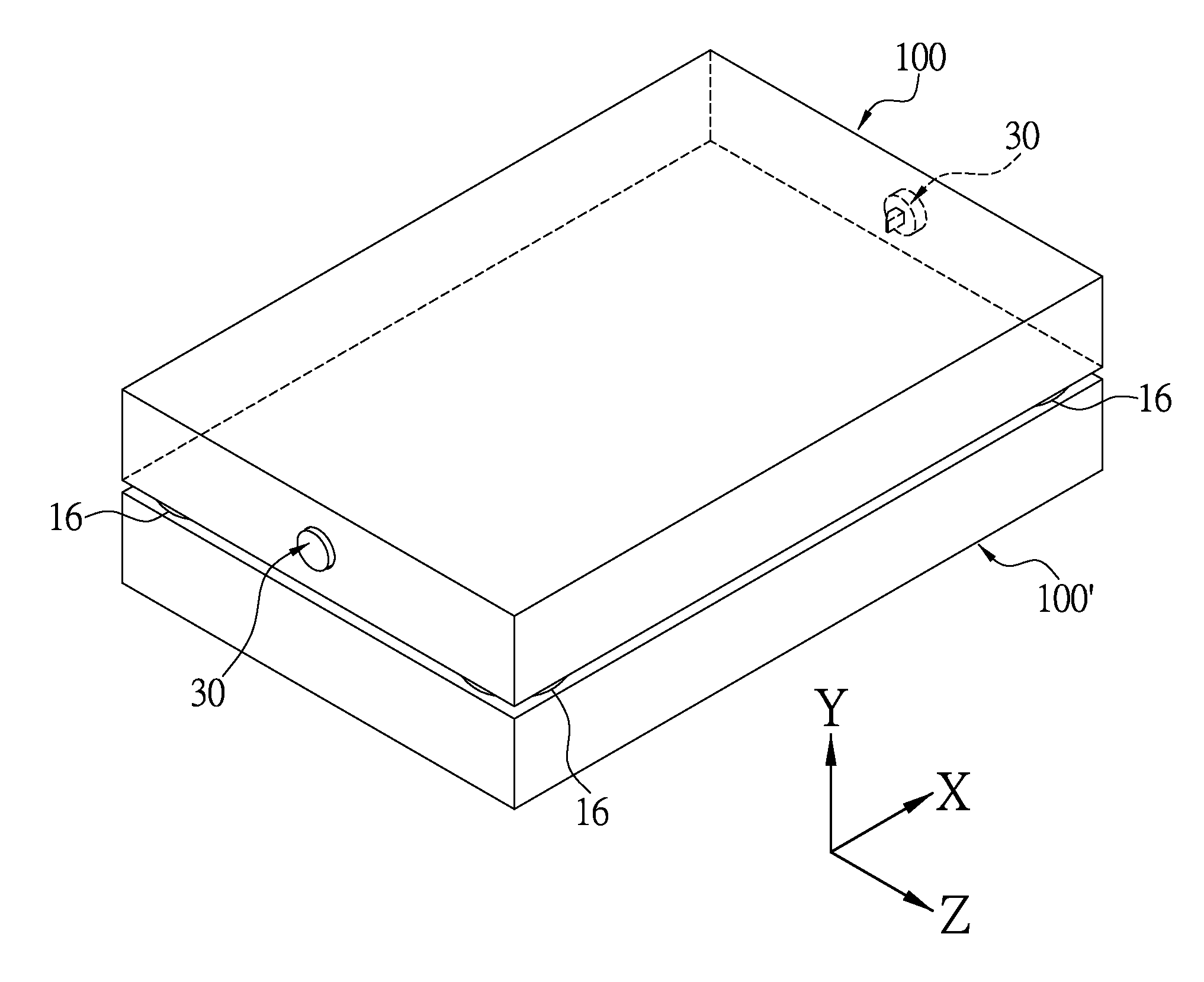
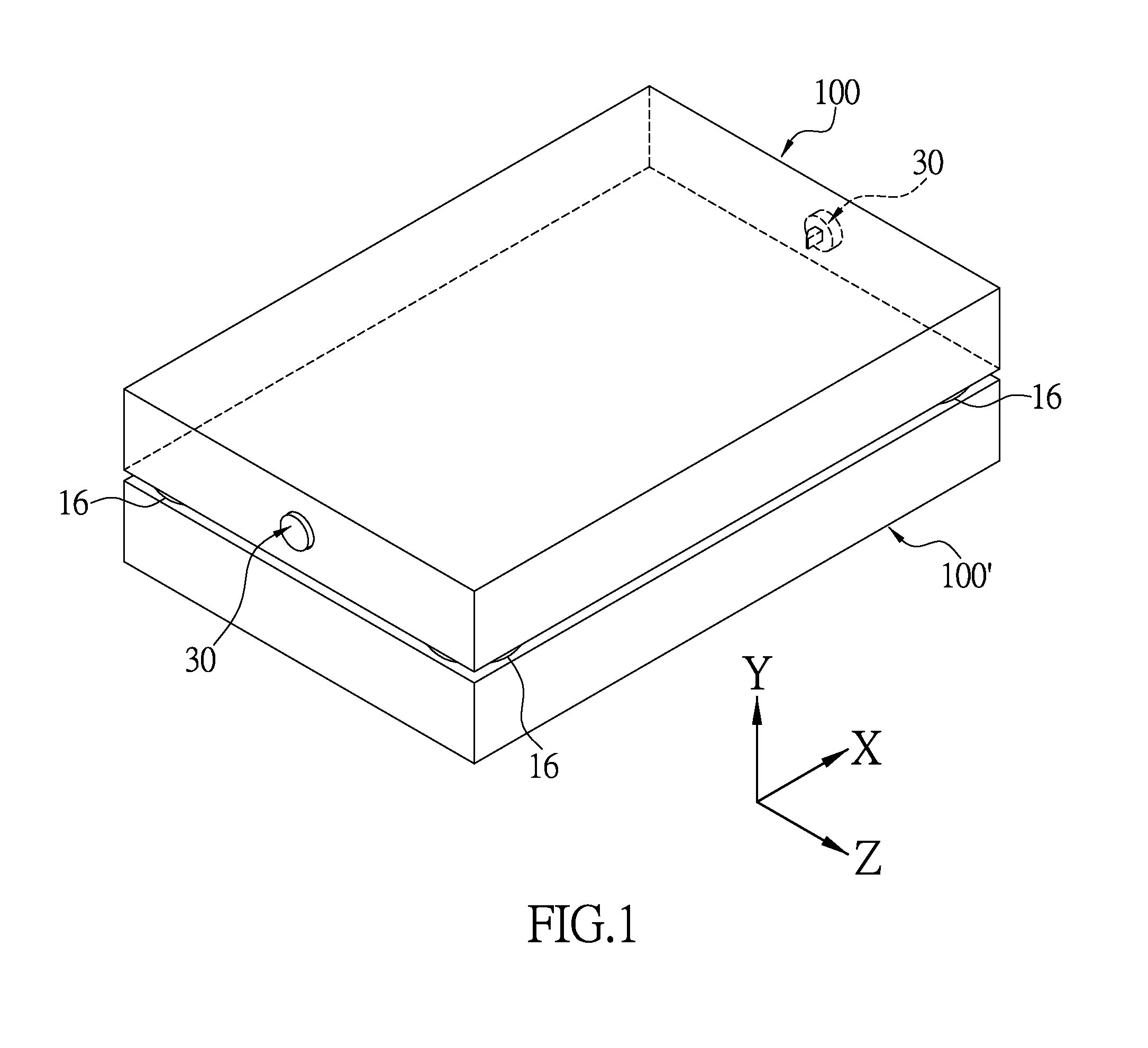
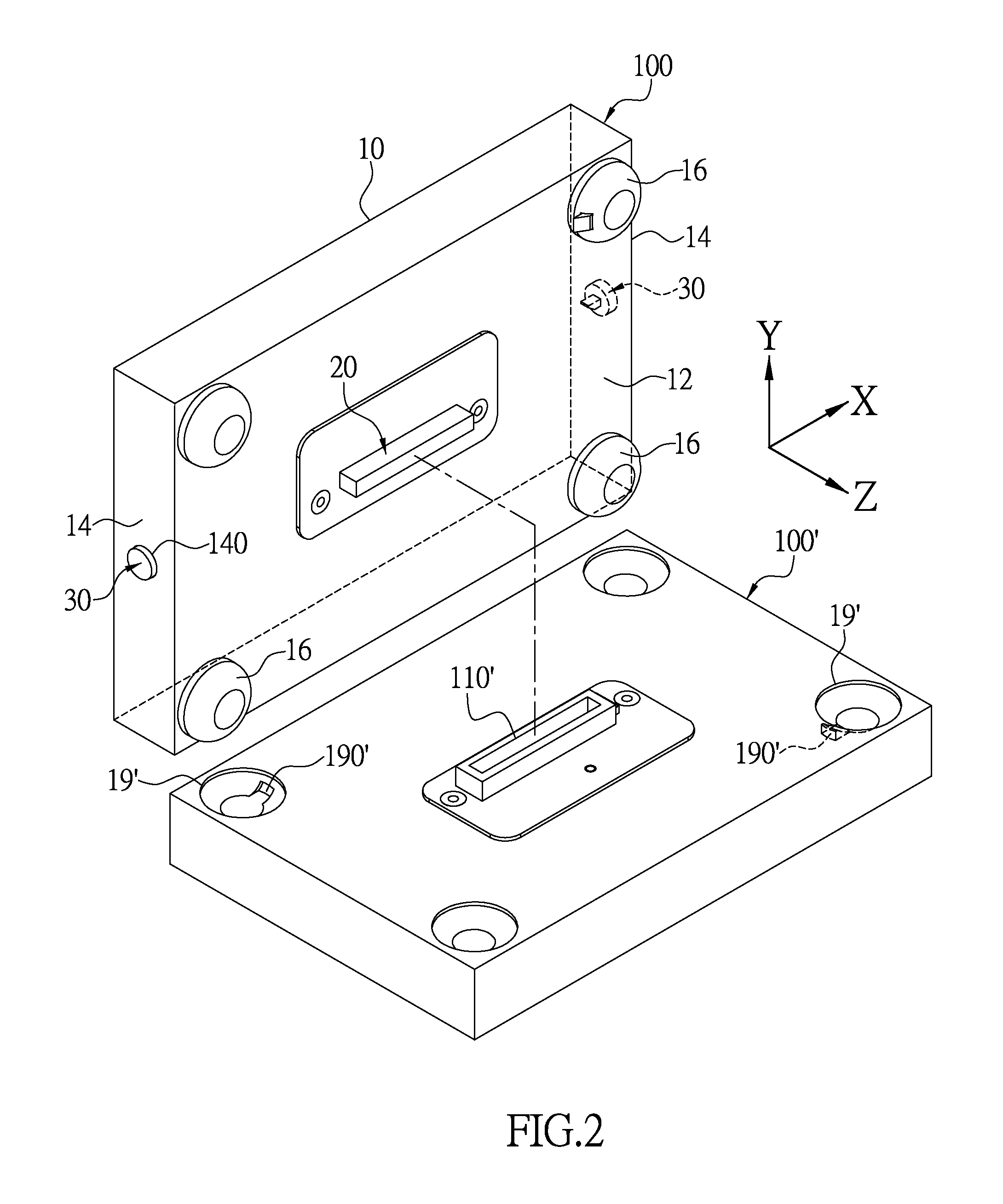
[0024]FIG. 1 and FIG. 2 are diagrams of an electronic device 100 with a latching bumper and another electronic device 100′ according to the present disclosure in respectively a stacked state and a separate state. The present disclosure provides an electronic device 100 with a latching bumper, alternately named as the first electronic device 100, which can be stacked on another electronic device 100′, alternately named as the second electronic device 100′. The electronic device 100 of the present disclosure includes a housing 10, an electrical connector 20, a latching mechanism 30 for latching the electronic device 100 onto the second electronic device 100′. The top surface of the second electronic device 100′ has a dock 110′ for mating with the electrical connector 20.

[0025]The housing 10 of the present embodiment is overall rectangular, has a bottom board 12, a plurality of side boards 14 connected to the bottom board 12, and four bumpers 16 disposed on the bottom board 12. The bot...

second embodiment

[0040]Referring to FIG. 6, the present embodiment differs from the first embodiment in that the electronic device 100 with a latching bumper replaces the string 318 with magnetic units. The lower rod 317 and the latching module 34a are respectively connected to two magnetic units 319, 348 which repel each other. The latching module 34a includes a latching beam 341, a pivot rod 346 extending from the latching beam 341, and a spring 343 sleeved on the pivot rod 341. The magnetic unit 348 is fixed on one end of the pivot rod 346. The bumper 16 has a protruding block 164 positioned below the pivot rod 348 and proximal to the latching beam 341. The two ends of the spring 343 respectively abut the magnetic unit 348 and the protruding block 164, and store a spring force under the normal locking position.

[0041]FIG. 7 shows a partial perspective view of the second embodiment at the locking position. After the user presses on the button 32, similar to the first embodiment, the lower rod 317 o...


PUM


Abstract

A stackable electronic device with latching bumper includes a housing, an electrical connector, a latching mechanism having a linking module, a latching module and a button. The housing has a bottom board, a side board formed with a button hole, and a bumper disposed on the bottom board formed with a latching hole. The linking module is disposed on an inner side of the side board, and has a first end extended into the button hole and a second end extended into the bumper. The latching module is movably disposed in the bumper between a locking position and an unlocking position. The second end is connected to the latching module. The button can be pressed for driving the first end to move the second end corresponding to the locking position and the unlocking position. The present disclosure also provides a stackable electronic device system.

Description

BACKGROUND OF THE DISCLOSURE[0001]1. Field of the Disclosure[0002]The present disclosure relates to an electronic device with latching bumper, latching bumper thereof, and a stackable electronic device system; in particular, to an electronic device which can be stacked and latch onto another electronic device by using latching bumpers.[0003]2. Description of Related Art[0004]Regarding methods of expanding electronic devices, prior art includes U.S. Pat. No. 7,602,603 “STACKABLE MODULAR COMPUTER HOUSING, AND COMPUTER DEVICE INCLUDING THE SAME,” which corresponds to TW 1306550. The disclosure provides a method of expanding electronic devices by stacking.[0005]Taking for example TV boxes and game consoles, they also use docking connectors for connecting by stacking. However, most docking connectors do not have latching mechanisms. Additionally, if the TV box or the game console does not have hot swap, the system can be damaged or shut down when the electronic device is accidentally pic...

Claims


Application Information

Patent Timeline
IPC IPC(8): H05K7/00
CPCH05K7/005H05K7/023
Inventor LIANG, JYUN-SHUOCHEN, HUNG-LI
Owner WISTRON CORP
Why Eureka
Try Eureka