Electronic device with latching bumper, latching bumper thereof, and stackable electronic device system
a technology of electronic devices and latching bumpers, applied in the direction of stackable modules, electrical devices, circuit arrangements on support structures, etc., can solve the problems of system damage or shutdown, no latching mechanism for the locking connector, etc., and achieve the effect of affecting the outward appearance of the electronic devi
- Summary
- Abstract
- Description
- Claims
- Application Information
AI Technical Summary
Benefits of technology
Problems solved by technology
Method used
Image
Examples
first embodiment
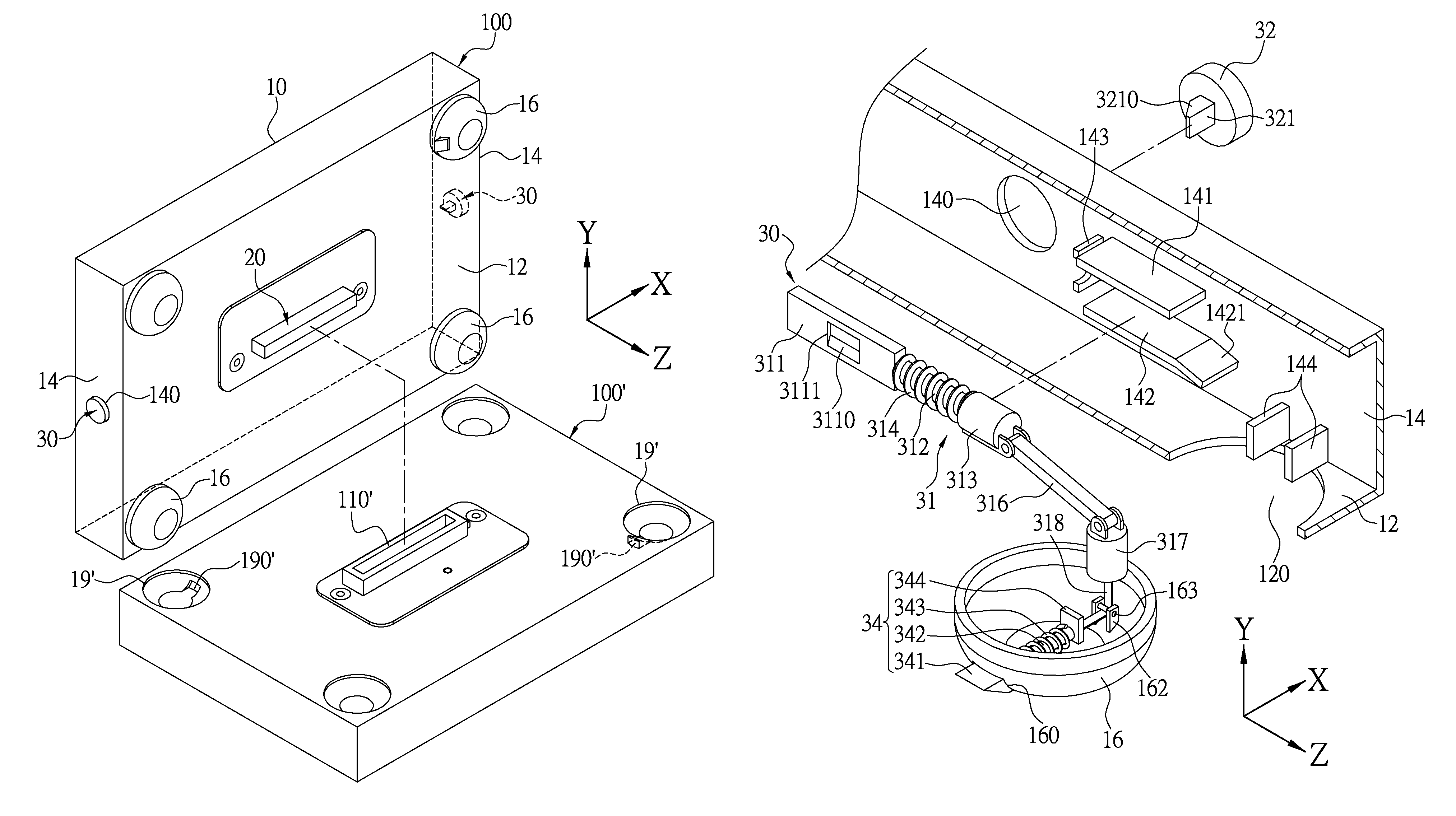
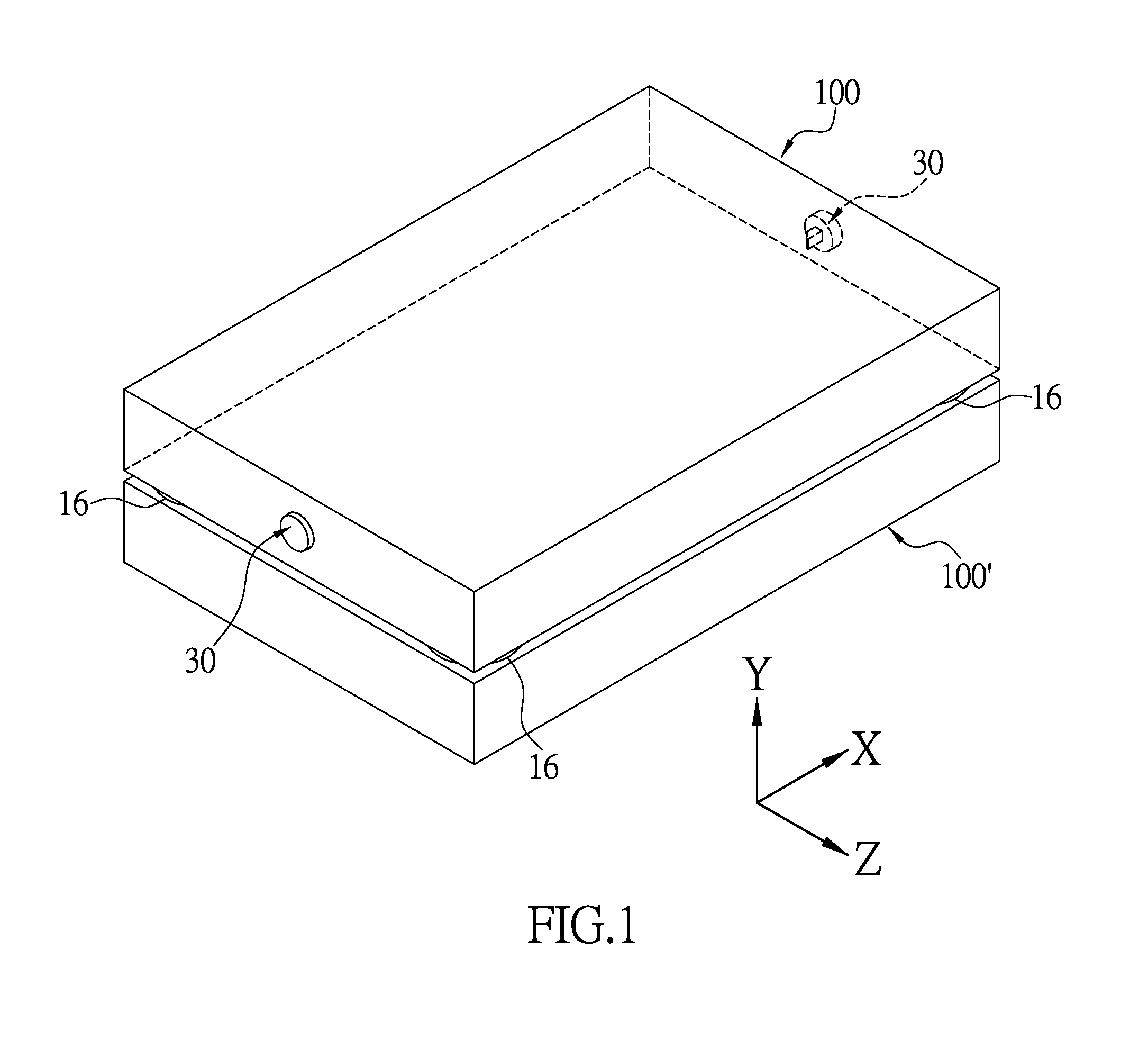
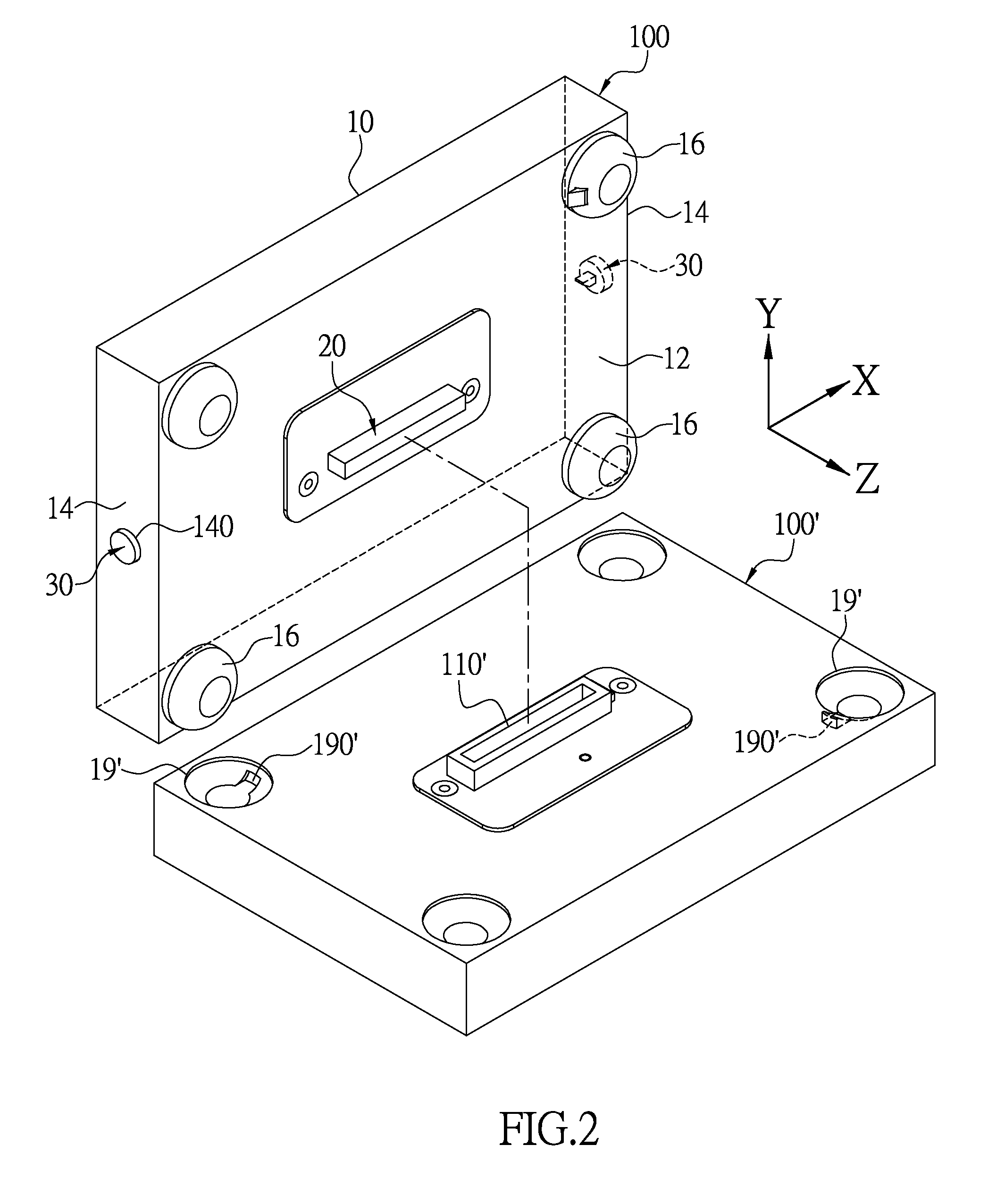
[0024]FIG. 1 and FIG. 2 are diagrams of an electronic device 100 with a latching bumper and another electronic device 100′ according to the present disclosure in respectively a stacked state and a separate state. The present disclosure provides an electronic device 100 with a latching bumper, alternately named as the first electronic device 100, which can be stacked on another electronic device 100′, alternately named as the second electronic device 100′. The electronic device 100 of the present disclosure includes a housing 10, an electrical connector 20, a latching mechanism 30 for latching the electronic device 100 onto the second electronic device 100′. The top surface of the second electronic device 100′ has a dock 110′ for mating with the electrical connector 20.
[0025]The housing 10 of the present embodiment is overall rectangular, has a bottom board 12, a plurality of side boards 14 connected to the bottom board 12, and four bumpers 16 disposed on the bottom board 12. The bot...
second embodiment
[0040]Referring to FIG. 6, the present embodiment differs from the first embodiment in that the electronic device 100 with a latching bumper replaces the string 318 with magnetic units. The lower rod 317 and the latching module 34a are respectively connected to two magnetic units 319, 348 which repel each other. The latching module 34a includes a latching beam 341, a pivot rod 346 extending from the latching beam 341, and a spring 343 sleeved on the pivot rod 341. The magnetic unit 348 is fixed on one end of the pivot rod 346. The bumper 16 has a protruding block 164 positioned below the pivot rod 348 and proximal to the latching beam 341. The two ends of the spring 343 respectively abut the magnetic unit 348 and the protruding block 164, and store a spring force under the normal locking position.
[0041]FIG. 7 shows a partial perspective view of the second embodiment at the locking position. After the user presses on the button 32, similar to the first embodiment, the lower rod 317 o...
PUM
 Abstract
Description
Claims
Application Information
 - R&D
- Intellectual Property
- Life Sciences
- Materials
- Tech Scout
- Unparalleled Data Quality
- Higher Quality Content
- 60% Fewer Hallucinations
Browse by: Latest US Patents, China's latest patents, Technical Efficacy Thesaurus, Application Domain, Technology Topic, Popular Technical Reports.
© 2025 PatSnap. All rights reserved.Legal|Privacy policy|Modern Slavery Act Transparency Statement|Sitemap|About US| Contact US: help@patsnap.com


