
Air battery system

a battery system and air technology, applied in the direction of electrolyte stream management, cell components, cell maintainance/servicing, etc., can solve the problem of increasing the volume of electrolytic solution, and achieve the effect of preventing the increase of inner pressure and reducing power outpu

Active Publication Date: 2014-09-25
NISSAN MOTOR CO LTD
View PDF4 Cites 5 Cited by
  • Summary
  • Abstract
  • Description
  • Claims
  • Application Information

AI Technical Summary

Benefits of technology

The present invention helps prevent a decrease in power output and an increase in inner pressure as reaction product accumulates and the electrolytic solution volume increases during a reaction.

Problems solved by technology

However, the unsolved problems with the above-described cell disclosed in Japanese Patent Unexamined Publication No.
These problems are caused by an increase in volume of the electrolytic solution with progress of the reaction because a reaction product is produced as a result of discharge of the battery.

Method used


Image

  • Air battery system
  • Air battery system
  • Air battery system

Examples


first embodiment

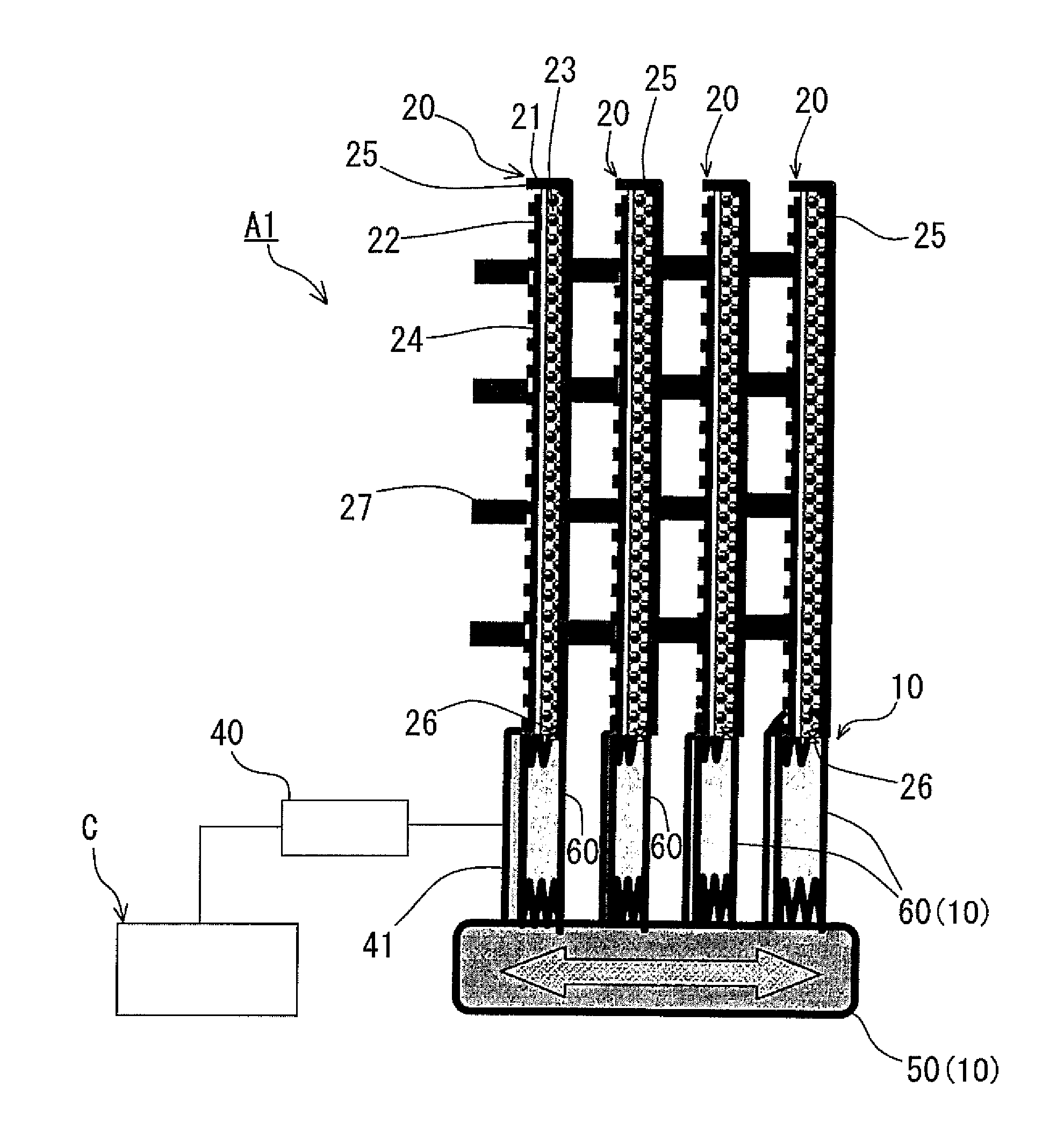
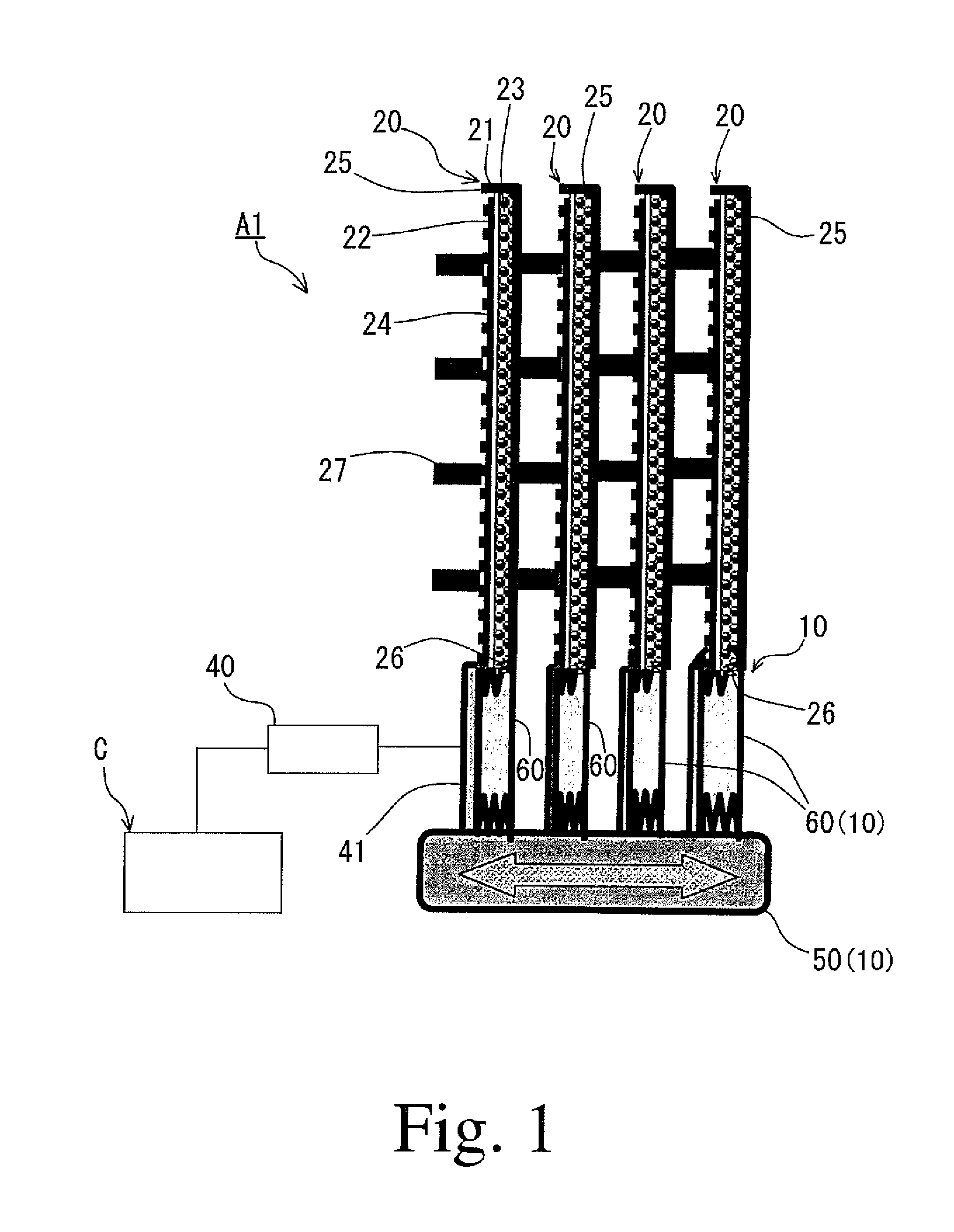
[0012]Hereinafter, an embodiment of the present invention will be described with reference to the drawings. FIG. 1 is a schematic explanatory view of an air battery system according to the present invention.

[0013]The air battery system A1 according to the first embodiment of the present invention includes a battery holder 10, a plurality of air batteries 20, a pressure and vibration generator 40, and a controller C.

[0014]The battery holder 10 includes a reservoir tank 50 and attaching / detaching members 60 that also serve as reaction product sumps, in which the attaching / detaching members 60 are disposed integrally with the reservoir tank 50 on the upper side thereof in the direction of the gravity vector. This configuration can simplify the structure, and can also cause gravity fall of the reaction product (described below) down to the attaching / detaching members 60. In the first embodiment, the air batteries 20, the attaching / detaching members 60 and the reservoir tank 50 are arran...

second embodiment

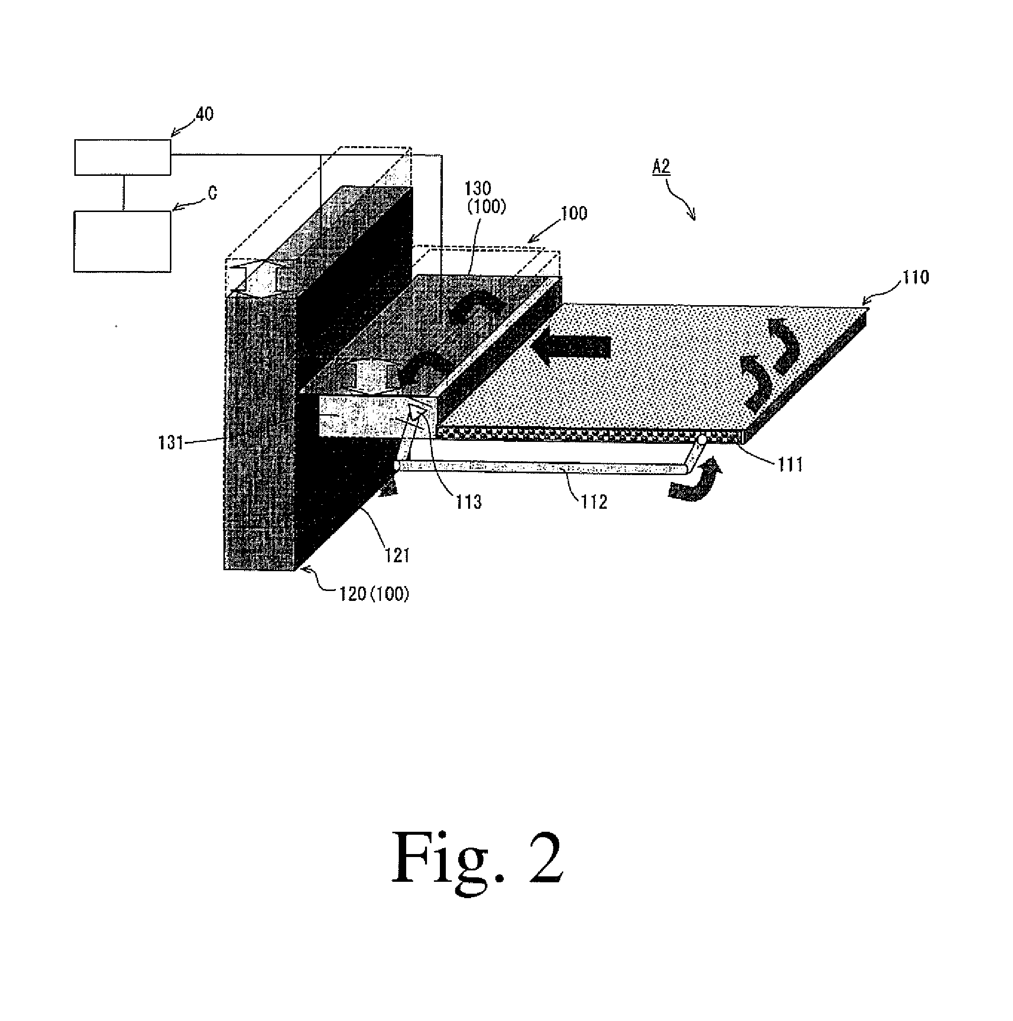
[0035]A supply pipe 112 for supplying the electrolytic solution is connected between a side part 131 of the attaching / detaching member 130 and a side part 111 of the air battery 110. Specifically, one end of the supply pipe 112 is connected to the side part 131 of the attaching / detaching member 130, and the other end is connected to the side part 111 of the air battery 110 at a position closer to the end opposite the attaching / detaching member 130. At one end of the supply pipe 112, a check valve 113 is disposed which opens only when the electrolytic solution is supplied to the air battery 110. In the second embodiment, the check valve 113 serves as a backflow preventing member.

[0036]In the air battery system A2 with the above-described configuration, the pressure and vibration generator 40 presses the attaching / detaching member 130 so as to inject the electrolytic solution into the air battery 110 through the check valve 113.

[0037]By injecting the electrolytic solution into the air...


PUM

PropertyMeasurementUnit
pressureaaaaaaaaaa
gravity vectoraaaaaaaaaa
sizeaaaaaaaaaa

Abstract

In an air battery system, a decrease in power output and an increase in inner pressure during discharge are prevented even when deposition of the reaction product increases with the discharge and the volume of the electrolytic solution increases with progress of the reaction. The air battery system includes an air battery a reservoir tank to reserve electrolytic solution to be supplied to the air battery and a reaction product sump to store reaction product produced in the air battery, the reaction product sump provided between the air battery and the reservoir tank.

Description

CROSS REFERENCE TO RELATED APPLICATION[0001]The present application claims priority to Japanese Patent Application No. 2011-229396, filed Oct. 19, 2011 and incorporated herein in its entirety.TECHNICAL FIELD[0002]The present invention relates to an air battery system that includes an air battery and a reservoir tank for reserving electrolytic solution to be supplied to the air battery.BACKGROUND[0003]An example of air batteries is disclosed in Japanese Patent Unexamined Publication No. Hei6-501128, where the air battery is referred to as a “cell”. The cell disclosed in Japanese Patent Unexamined Publication No. Hei6-501128 includes a cathode and an anode facing the cathode, a vertically extending electrolysis region between them and a housing to contain electrolyte.[0004]The housing includes a sump with an upper and a lower region, said sump being of a size to contain enough aluminum hydroxide precipitate so as to permit the cell to continue operating after saturation of the electro...

Claims


Application Information

Patent Timeline
Patent Type & Authority Applications(United States)
IPC IPC(8): H01M6/50H01M12/04H01M50/77
CPCH01M6/5077H01M12/04H01M8/04276H01M12/065H01M2/38H01M50/70Y02E60/50H01M50/77
Inventor TSUKDA, YOSHIKOOGIHARA, WATARUMIYAZAWA, ATSUSHINAGAYAMA, MORICHIBA, NOBUTAKA
Owner NISSAN MOTOR CO LTD
Learn More