
Method and installation for manufacturing thin metal strip

a technology of thin metal strips and manufacturing methods, applied in the direction of thin material handling, web handling, transportation and packaging, etc., can solve the problems of deteriorating productivity, not being solved, and having a widthwise length (depth) of not more than 1 mm,

Active Publication Date: 2014-10-02
JFE STEEL CORP
View PDF0 Cites 0 Cited by
  • Summary
  • Abstract
  • Description
  • Claims
  • Application Information

AI Technical Summary

Benefits of technology

The patent describes a method to reduce breakage and cracks in thin metal strips during manufacturing processes. By adjusting the distance between the cooling roll and the suction type belt conveyor, and the ratio of the suction width to the width of the metal strip, microcracks can be minimized. This technique also helps to improve the productivity and prevent the microcracks from causing breakage when the metal strip is worked into a product.

Problems solved by technology

According to the inventors' researches, however, microcracks having a widthwise length (depth) of not more than 1 mm, which are generated in widthwise end portions (edge portions) of the thin metal strip at a level confirmed only by a microscope, are not solved even in the use of the above techniques.
However, the microcracks may be a starting point of breakage when the thin metal strip as a starting material is worked into a product, and is a cause of considerably deteriorating the productivity even if the generation frequency is low.

Method used


Image

  • Method and installation for manufacturing thin metal strip
  • Method and installation for manufacturing thin metal strip
  • Method and installation for manufacturing thin metal strip

Examples


example

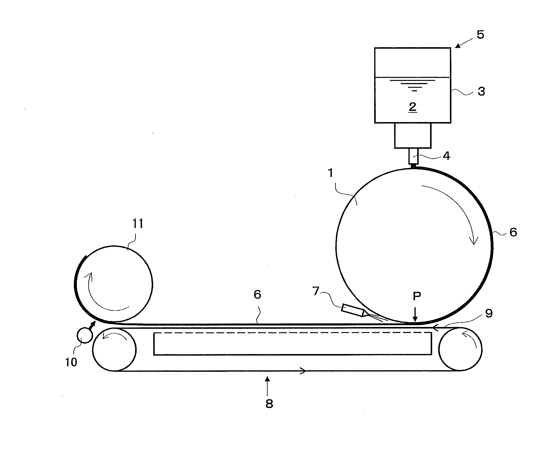
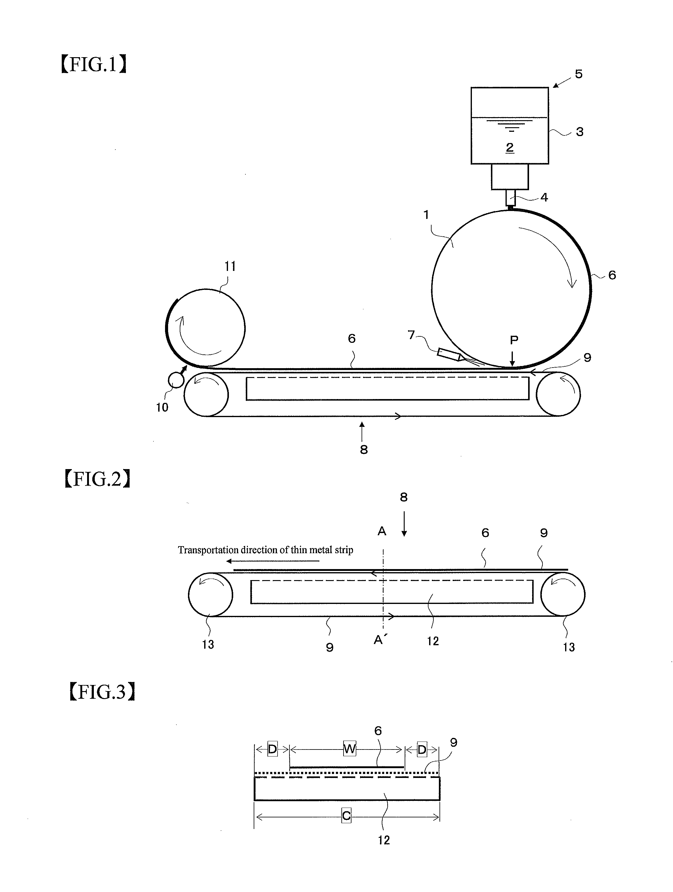
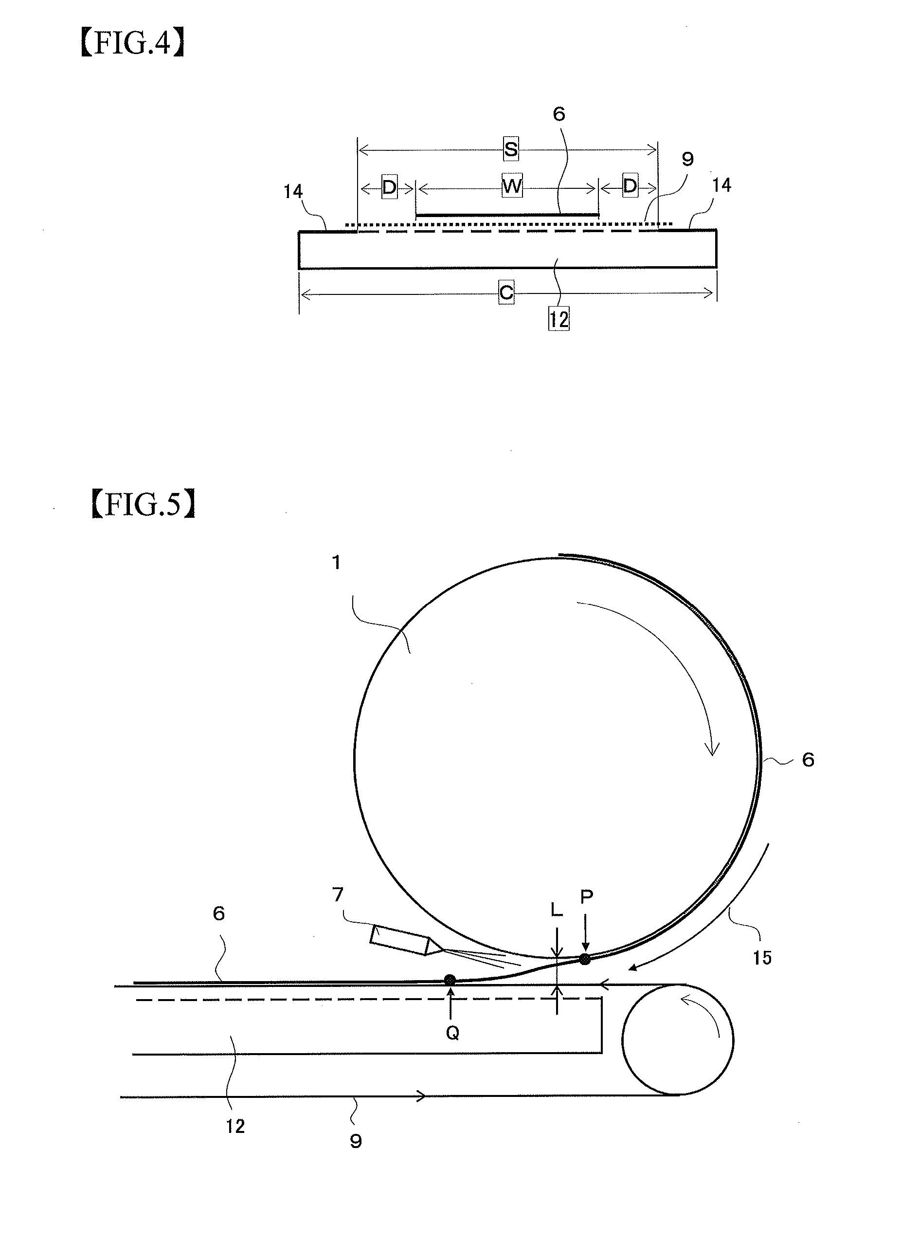
[0039]An experiment of manufacturing a thin metal strip with a chemical composition comprising C: 1.2 at %, Si: 8.7 at %, B: 9 at % and the remainder being substantially Fe is conducted using an installation for the manufacture of thin metal strip shown in FIG. 1 having a suction box of a structure shown in FIG. 4. Concretely, molten metal having the above chemical composition and heated to a temperature of 1320° C. is kept in a hot metal keeping vessel, poured from a slit nozzle arranged in the lower part of the hot metal keeping vessel onto an outer peripheral surface of a copper alloy cooling roll rotating sat a high peripheral speed of 30 m / s and rapidly solidified to form a thin metal strip having a thickness of 25 μm. Thereafter, compression air is blown to the thin metal strip from an air nozzle directing substantially to a tangential direction of the outer peripheral surface of the cooling roll at 30 m / s to separate the thin metal strip from the outer peripheral surface of t...


PUM

PropertyMeasurementUnit
Lengthaaaaaaaaaa
Lengthaaaaaaaaaa
Lengthaaaaaaaaaa

Abstract

A method for manufacturing a thin metal strip by pouring and rapidly solidifying molten metal onto a cooling roll rotating at a high speed to form a thin metal strip having a width of 50˜350 mm, blowing compression gas from substantially a tangential direction of the cooling roll toward the thin metal strip to separate the thin metal strip from the cooling roll, adsorbing the separated thin metal strip with a permeable belt of a suction type belt conveyor, and transporting to a take-up reel to wind in form of a coil, the thin metal strip is adsorbed by the belt under conditions that a nearest approaching distance L between the cooling roll and the suction type belt conveyor is 2·50 mm and a suction width S of a suction box arranged in the suction type belt conveyor is 1.2·2.5 times of a width W of the thin metal strip.

Description

CROSS REFERENCE TO RELATED APPLICATIONS[0001]This is the U.S. National Phase application of PCT / JP2012 / 079334, filed Nov. 13, 2012, which claims priority to Japanese Patent Application No. 2011-248384, filed Nov. 14, 2011, the disclosures of each of these applications being incorporated herein by reference in their entireties for all purposes.FIELD OF THE INVENTION[0002]This invention relates to a method for manufacturing a thin metal strip by rapidly solidifying molten metal with a cooling roll rotating at a high speed and an installation used in the manufacturing method.BACKGROUND OF THE INVENTION[0003]Rapid solidification of molten metal with a cooling roll rotating at a high speed, or so-called “rapid cooling process” has been developed as a technique for manufacturing thin metal strips. In this case, it is one of important issues that the thin metal strip manufactured at the high speed is separated from the cooling roll and transported to a take-up reel and wound in form of a c...

Claims


Application Information

Patent Timeline
IPC IPC(8): B22D11/06
CPCB22D11/062B22D11/0694B22D11/0682B22D11/0611B22D11/0631B65H20/10B65H2301/5144B65H2406/122B65H2406/3124B65H2701/173
Inventor TAKASHIMA, MINORUOKABE, SEIJISHIGA, NOBUO
Owner JFE STEEL CORP
Learn More