Dosing system and dosing method

a technology of dosing system and dosing method, which is applied in the direction of liquid transfer device, volume metering, instruments, etc., can solve the problems of system reaching its technical limits, and the challenge of high-precision dosing becomes even greater

Active Publication Date: 2014-10-02
VERMES MICRODISPENSING GMBH
View PDF9 Cites 16 Cited by
  • Summary
  • Abstract
  • Description
  • Claims
  • Application Information

AI Technical Summary

Benefits of technology

[0033]It has also been proven as advantageous if a maximum travel path of an actuator of the actuator system and / or a maximum path of the actuating element is limited by a stop device. Here, the term stop device can be very broadly interpreted: a stop device can (as has already been described) be a mechanical element, on which the actuator of the actuating system and / or the actuating element comes into contact in a certain position. However, a stop device can also be realized through appropriate programming or pre-setting of a control of the actuator, i.e. by means of software, for example. Here it is sufficient to use electronic path control in the form of path limiting. Overall, through limiting the path of the actuator of the actuator system and / or of the actuating element it is ensured that the paths of the actuator and the closure element can be adjusted in a defined manner and thus the forces occurring between the actuating element and the closure element can be estimated and defined beforehand.
[0034]In addition to the actuator system which moves the actuating element and ultimately the closure element in at least the closure direction, it can be envisaged that the closure element and / or the actuator system is pushed in an opening direction and / or in the closure direction in a spring manner. Such spring-based force exertion on the actuating element and respectivlely on the closure element can, for example when acting in the opening direction, cause the closure element and / or the actuating element to be pushed back into an opening position so that for this movement a separate automatic actuator is not necessary. In this way the dosing system is more simply and effectively designed.
[0035]In order to keep a stop device positioned at all times in such a way that it exerts its limiting effect on the path of the actuator system and / or the closure element, it is preferably envisaged that its position can be adjusted and particularly preferably is spring-preloaded. The stop device is not therefore firmly installed, but can be varied in position and then fixed. Spring-loaded fixing has proven to be a simple measure in order to do this.

Problems solved by technology

A particular challenge consists in the high-precision delivery of the dosing materials to the target surface, i.e. at the right time, at the right place and in a precisely dosed quantity.
The challenge of high-precision dosing becomes even greater if the dosing material is not an easily flowing substance, with a similar consistency to that of water, but a relatively viscous medium.
In high-precision fine applications, especially in the field of micro-dosing and particularly in the field of the above dosing materials, such systems reach their technical limits, more particularly because of the too slow mechanics.

Method used


Image

  • Dosing system and dosing method
  • Dosing system and dosing method
  • Dosing system and dosing method

Examples


Embodiment Construction

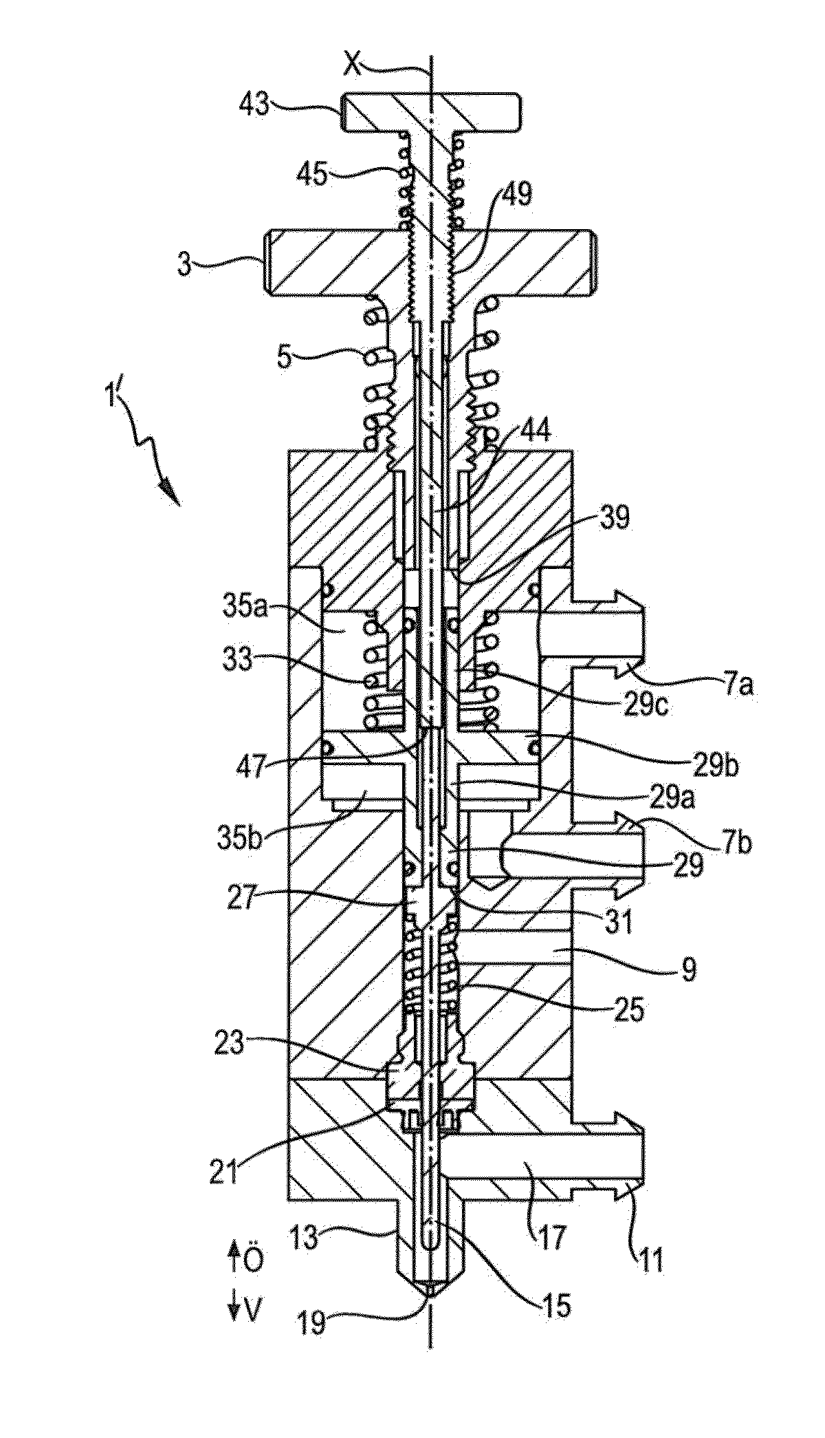
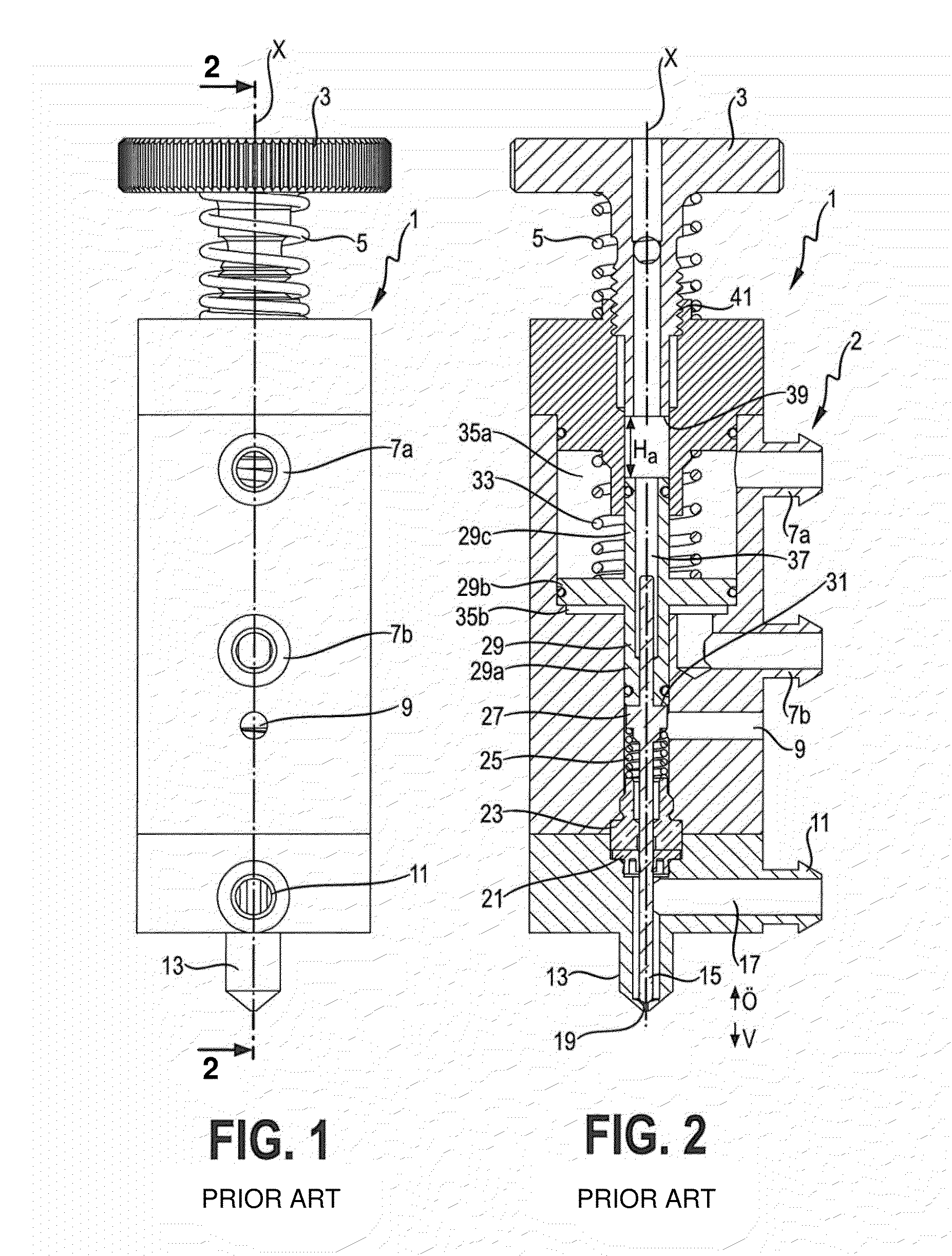
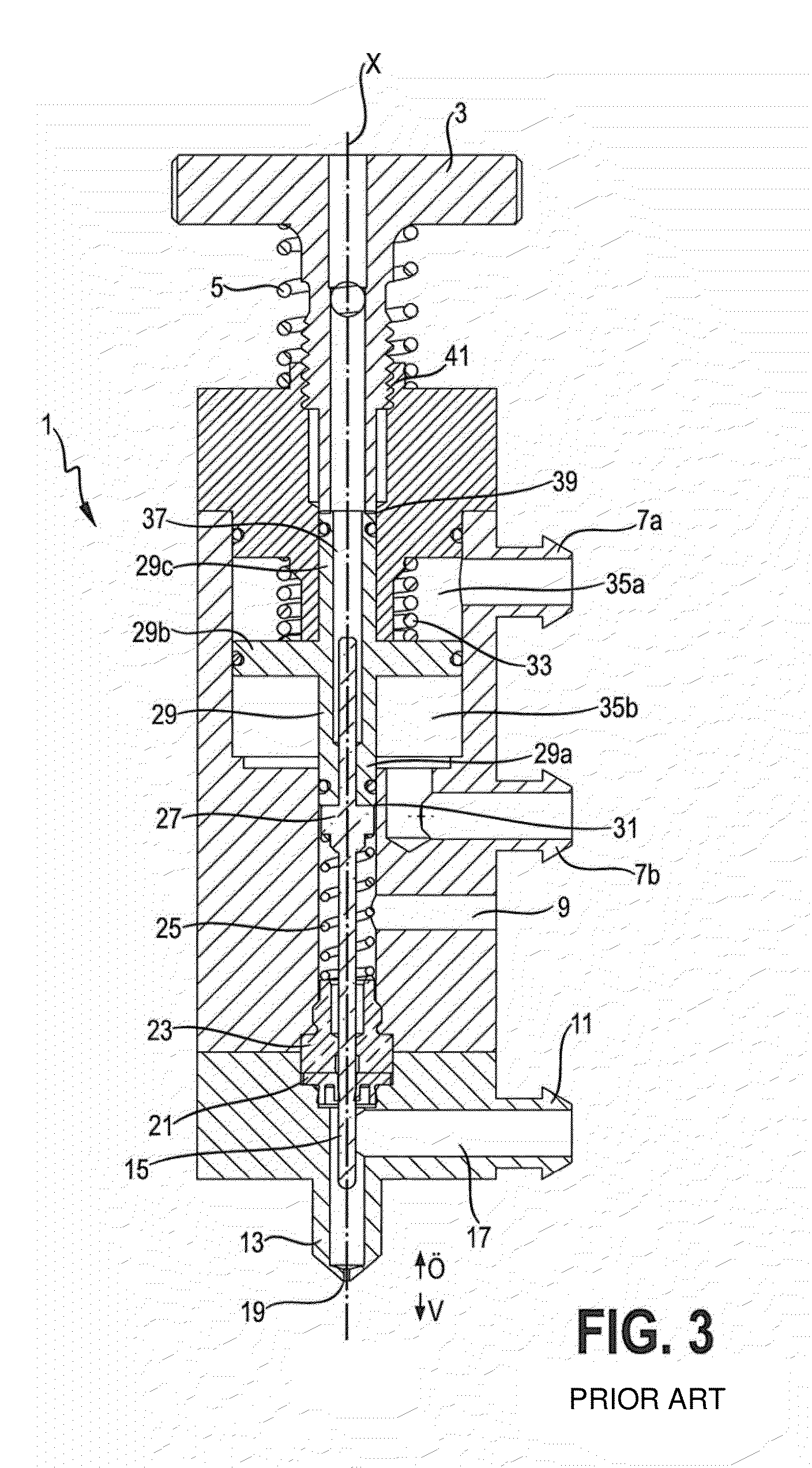
[0048]FIGS. 1 and 2 show a dosing system 1 in accordance with the prior art. It comprises an actuator system 2 and a nozzle 13, whereby a closure element 15 in the form of a plunger 15 can be moved by the actuator system 2 in a closure direction V of the nozzle 13, i.e. more particularly in the direction of an outlet opening 19 of the nozzle 13, or in an opening direction Ö away from this outlet opening 19. This closing and opening movement takes place along an effect axis X arranged centrally within the dosing system 1 and defined by the alignment of the plunger 15 within the dosing system 1.

[0049]In this form of embodiment the actuator system 2 is in the form of a pneumatic or hydraulic system. This means that an actuator 29 of an actuator system 2 acting as an actuating element 29 can be moved to and fro by pressurised gas or pressurised fluid in a cylinder, in which are located an upper chamber 35a and a lower chamber 35b, which are separated from one another by the actuator 29 ...


PUM


Abstract

A dosing system for a liquid or viscous dosing material, including an actuator system, that has at least one actuating element and a nozzle with an outlet opening. The dosing system is designed so that during a movement in a closure direction the actuating element is initially moved in a first partial movement in such a way that the actuating element is separated from the closure element at a stop location, intended for that purpose, and then comes into contact with the closure element at the stop location and exerts an impulse on the closure element. This also relates to a corresponding dosing method.

Description

FIELD OF THE INVENTION[0001]The present invention relates to a dosing system for a liquid or viscous dosing material. It also relates to a method of dosing a liquid or viscous dosing material.BACKGROUND OF THE INVENTION[0002]The dispensing (more particularly of an as precisely determined amount as possible), i.e. the dosing, of liquid or viscous dosing materials, for example, adhesives, paints, printing varnishes, conductive substances bound in a binder system such as soldering pastes, converter materials for LEDs etc. is intended for the targeted application of such dosing materials, for example on target surfaces. For instance, electronic circuit boards are specifically and precisely provided with conductive substances, replacing previously necessary time-consuming and costly processes, such as scraping processes, based on masking. A particular challenge consists in the high-precision delivery of the dosing materials to the target surface, i.e. at the right time, at the right plac...

Claims


Application Information

Patent Timeline
Patent Type & Authority Applications(United States)
IPC IPC(8): B67D3/00
CPCB05C11/1028B05C5/0225B05C5/0212B05C11/1034G01F11/021H05K3/1241H05K2203/0126
Inventor FLIESS, MARIOSTAEDTLER, JUERGEN
Owner VERMES MICRODISPENSING GMBH
Why Eureka
Try Eureka