
Infrared sensor

a technology of infrared sensor and infrared light, which is applied in the field of infrared sensors, can solve problems such as the degradation of detection precision, and achieve the effect of suppressing the occurren

Active Publication Date: 2014-10-02
PANASONIC INTELLECTUAL PROPERTY MANAGEMENT CO LTD
View PDF11 Cites 18 Cited by
  • Summary
  • Abstract
  • Description
  • Claims
  • Application Information

AI Technical Summary

Benefits of technology

The invention is about an infrared sensor that helps avoid distortion in the lens. The goal is to improve the quality of the sensor's image.

Problems solved by technology

In the infrared sensor, there is a concern about degradation in detection precision because an off-axis aberration occurs in a case where infrared (an off-axis light) emitted from an off-axis object point is detected.

Method used


Image

  • Infrared sensor
  • Infrared sensor
  • Infrared sensor

Examples


Embodiment Construction

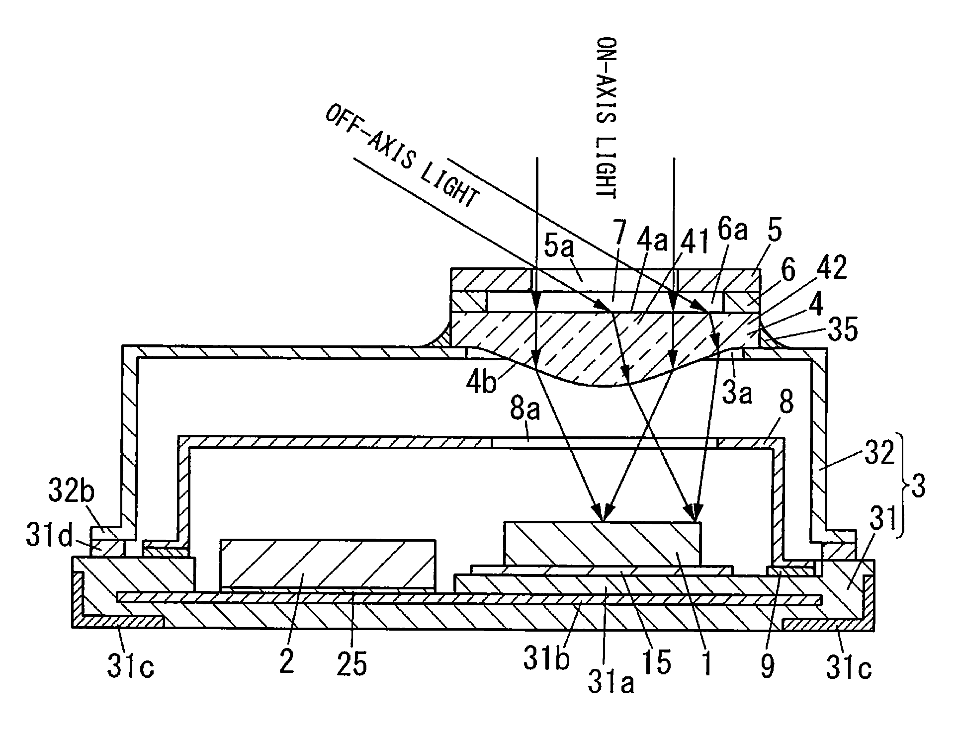
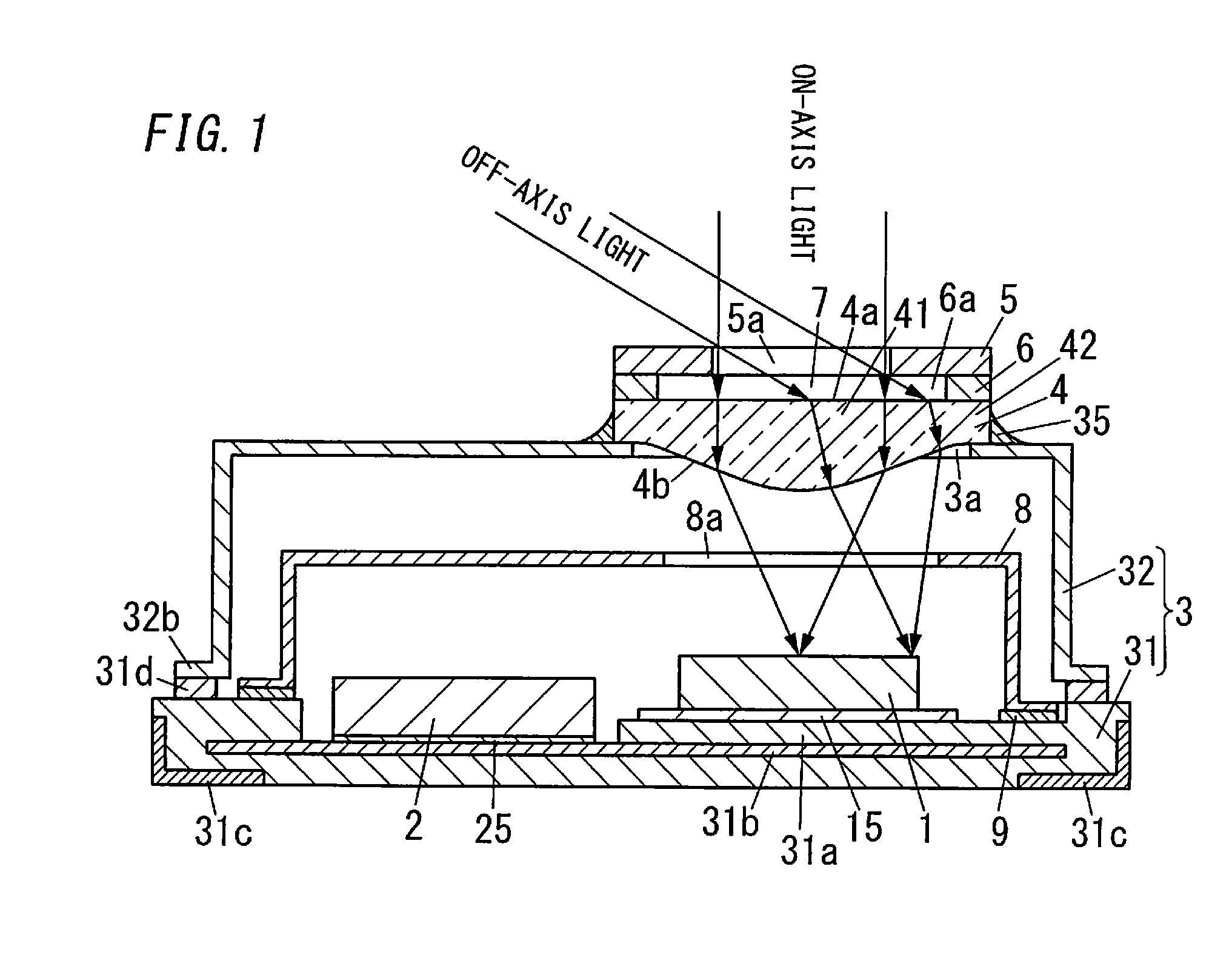
[0016]Hereinafter, an infrared sensor in an embodiment is explained with reference to FIG. 1.

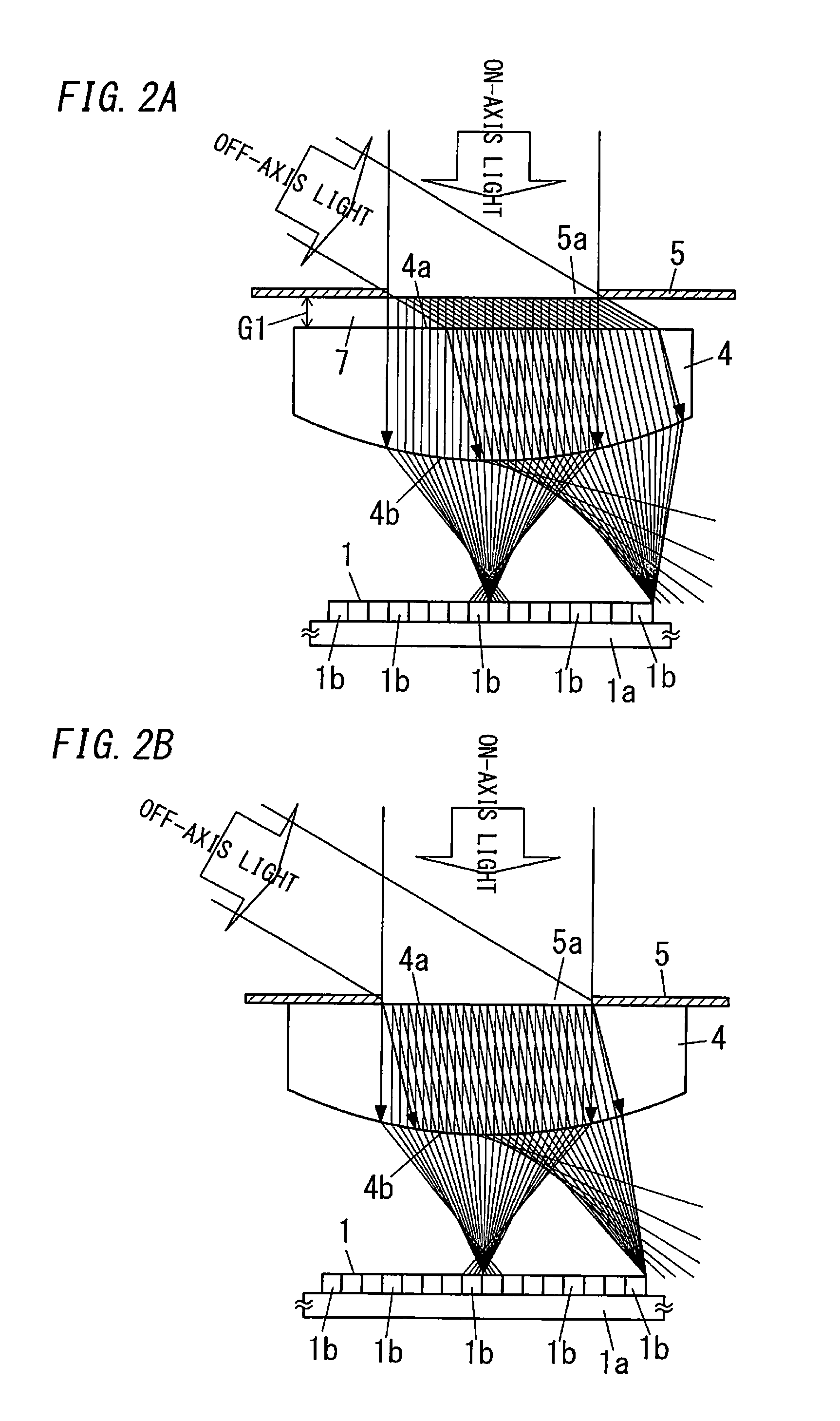
[0017]The infrared sensor includes an infrared detecting device 1, a package 3 housing the infrared detecting device 1, and a lens 4 that is disposed so as to close a window hole 3a, above the infrared detecting device 1, of the package 3. That is, in the infrared sensor, the package 3 includes the window hole 3a above the infrared detecting device 1, and the lens 4 is disposed so as to close the window hole 3a. The infrared sensor also includes: a member 5 that is disposed at a side of an upper surface 4a of the lens 4 and includes an opening 5a defining an infrared transmission region in the lens 4; and a spacer 6 that intervenes between the member 5 and the lens 4.

[0018]The package 3 includes a package body 31 on which the infrared detecting device 1 is mounted, and a package lid 32 joined to the package body 31. The package lid 32 of the package 3 is formed with the aforementioned window...


PUM


Abstract

An infrared sensor includes: an infrared detecting device; a lens disposed above the infrared detecting device; an member that is disposed at a side of an upper surface of the lens and includes an opening; and a gap that intervenes between the member and the lens and has a wider range than the opening.

Description

CROSS REFERENCE TO RELATED APPLICATIONS[0001]This application is a continuation application of International Application No. PCT / JP2012 / 079808, filed on Nov. 16, 2012, entitled “INFRARED SENSOR”, which claims priority based on Article 8 of Patent Cooperation Treaty from prior Japanese Patent Application No. 2011-273619, filed on Dec. 14, 2011, the entire contents of which are incorporated herein by reference.TECHNICAL FIELD[0002]The disclosure relates to an infrared sensor.BACKGROUND ART[0003]Conventionally, there is known an infrared sensor that includes an infrared detecting device, a package housing the infrared detecting device, and a semiconductor lens closing a window hole, in front of the infrared detecting device, of the package (e.g., JP Pub. Nos. 2011-220939 (Patent Document 1), 2007-292721 (Patent Document 2) and 2010-237117 (Patent Document 3)).[0004]In the infrared sensor, there is a concern about degradation in detection precision because an off-axis aberration occurs ...

Claims


Application Information

Patent Timeline
Patent Type & Authority Applications(United States)
IPC IPC(8): G01J1/04
CPCG01J1/0407G01J1/0437G01J1/0411G01J5/0831G01J5/0025G01J5/0806G01J5/0235G01J1/04G01J5/02G01J5/06
Inventor OKUDO, TAKAFUMIMIYATAKE, TAKAHIROSANAGAWA, YOSHIHARUKIRIHARA, MASAONISHIJIMA, YOICHIAKETA, TAKANORITOMOIDA, RYO
Owner PANASONIC INTELLECTUAL PROPERTY MANAGEMENT CO LTD
Learn More