Terminal including multiband antenna as conductive border

a multi-band antenna and conductive layer technology, applied in the direction of waveguide type devices, resonant antennas, independent non-interacting antenna combinations, etc., can solve the problems of deteriorating antenna radiation efficiency, surface conductive layer peeling or splitting, disturbing transmission/reception, etc., to improve antenna performance and ensure durability and design competitiveness.

Active Publication Date: 2014-10-02
PANTECH CORP
View PDF2 Cites 70 Cited by
  • Summary
  • Abstract
  • Description
  • Claims
  • Application Information

AI Technical Summary

Benefits of technology

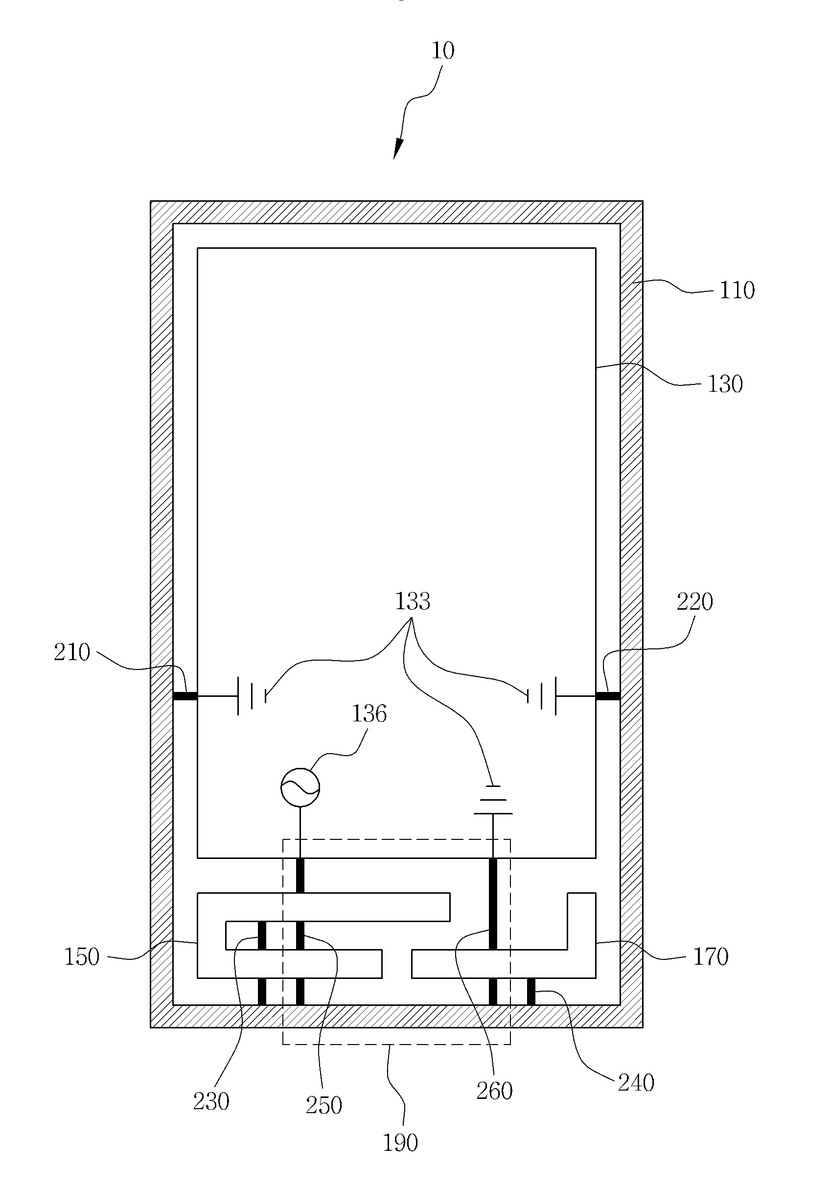
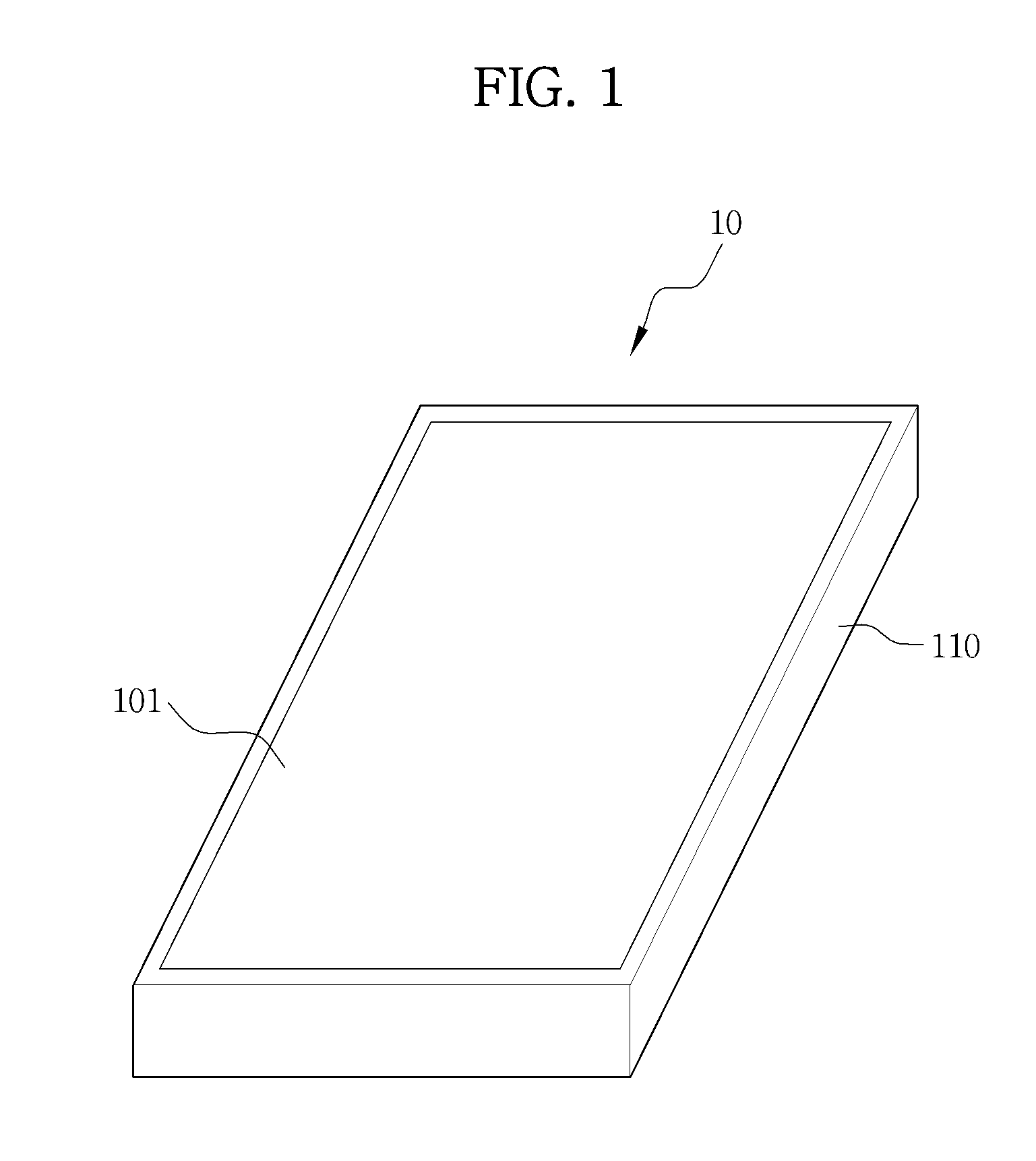
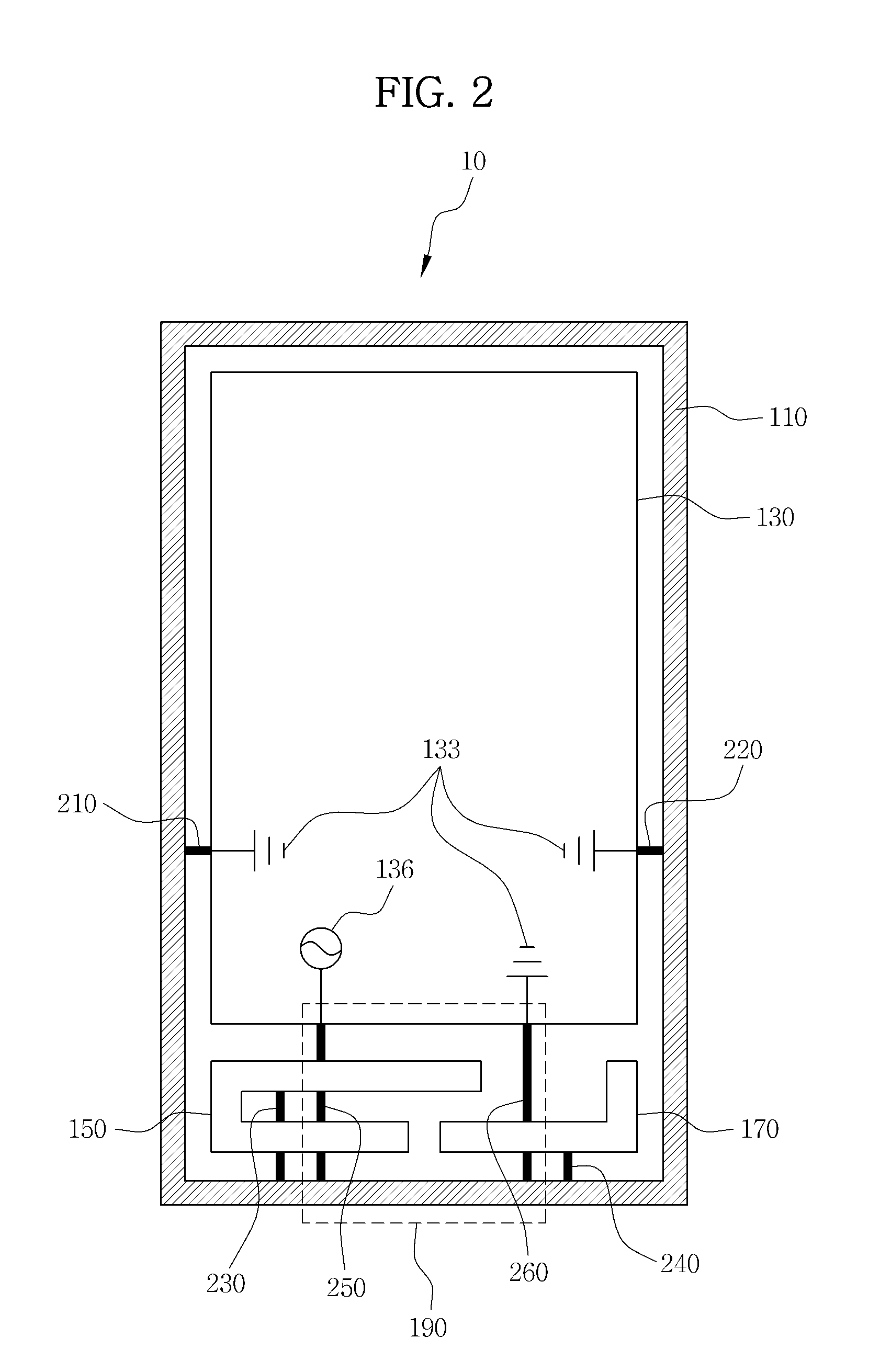
[0012]In accordance with aspects of the present invention, there may be provided a terminal, which secures durability and design competitiveness and improves antenna performance through an application of a continuous conductive border

Problems solved by technology

In the case of forming a thin conductive layer on the border surface of the housing, the surface conductive layer may peel off or split into pieces due to scratching, external impact, and the like, or by long or excessive use over time.
However, an electric current that flows to the antenna may induce current in the housing, thereby disturbing the transmission/reception of signals, and this may cause deterioration of the radiation efficiency of the antenna.
Accordingly, the structure to which the method of forming the metal housin

Method used


Image

  • Terminal including multiband antenna as conductive border
  • Terminal including multiband antenna as conductive border
  • Terminal including multiband antenna as conductive border

Examples


Embodiment Construction

[0040]The invention is described more fully hereinafter with reference to the accompanying drawings, in which embodiments of the invention are shown. This invention may, however, be embodied in many different forms and should not be construed as limited to the embodiments set forth herein. Rather, these embodiments are provided so that this disclosure is thorough, and will fully convey the scope of the invention to those skilled in the art. It will be understood that for the purposes of this disclosure, “at least one of X, Y, and Z” can be construed as X only, Y only, Z only, or any combination of two or more items X, Y, and Z (e.g., XYZ, XZ, XYY, YZ, ZZ). Throughout the drawings and the detailed description, unless otherwise described, the same drawing reference numerals are understood to refer to the same elements, features, and structures. The relative size and depiction of these elements may be exaggerated for clarity.

[0041]The terminology used herein is for the purpose of descr...


PUM

PropertyMeasurementUnit
Lengthaaaaaaaaaa
Electrical conductoraaaaaaaaaa
Distanceaaaaaaaaaa

Abstract

A conductive border surrounds a terminal along a direction. A mobile terminal includes a wireless transmission/reception circuit to output a signal for a wireless communication of the mobile terminal; a conductive border that forms side surfaces of the mobile terminal; a ground element electrically connected to the conductive border; a first antenna element electrically connected to the conductive border and the wireless transmission/reception circuit; and a second antenna element electrically connected to the conductive border and the ground element.

Description

CROSS-REFERENCE TO RELATED APPLICATIONS[0001]This application claims priority from and the benefit under 35 U.S.C. §119(a) of Korean Patent Application No. 10-2013-0034406, filed on Mar. 29, 2013, which is hereby incorporated by reference in its entirety for all purposes as if fully set forth herein.BACKGROUND[0002]1. Field[0003]Exemplary embodiments of the present invention relate to a terminal including a multiband antenna as a conductive border.[0004]2. Discussion of the Background[0005]As various electronic devices have been developed and used in daily life, new terminals, which not only have good qualities and functions but also have appealing designs, have been demanded. In particular, a method for forming a metal housing of a conductive material on the exterior of a terminal has been used to protect the terminal from external impact and to emphasize more appealing design features of the product.[0006]In the related art, a method that applies a conductive material as the exter...

Claims


Application Information

Patent Timeline
IPC IPC(8): H01Q1/24H01Q5/10
CPCH01Q1/243H01Q7/00H01Q9/42H01Q21/28H01Q5/371H01Q5/378Y10T29/49016H01Q1/22H01Q1/48H04B1/40H01Q5/10
Inventor YOO, KYOUNG SANGKANG, MYUNG GU
Owner PANTECH CORP
Why Eureka
Try Eureka