
Long life pinion shaft and method for manufacturing thereof

a technology of pinion shaft and long life, which is applied in the field of pinion shaft, can solve the problems of unavoidable phenomenon, generation of edge load, damage to and peeling of the surface of the pinion shaft, etc., and achieve the effects of long life, secure durability and dimensional stability, and long li

Inactive Publication Date: 2014-01-09
HYUNDAI MOTOR CO LTD +1
View PDF3 Cites 4 Cited by
  • Summary
  • Abstract
  • Description
  • Claims
  • Application Information

AI Technical Summary

Benefits of technology

The present invention provides a durable pinion shaft with better performance and a method for its manufacturing. The outer diameter portion is made of high carbon alloy steel and the inner diameter portion is made of medium carbon steel, which increases the overall hardness and reduces bending of the shaft. The method includes a hydrostatic extrusion step and a single heat treatment step, which improves durability and reduces production costs.

Problems solved by technology

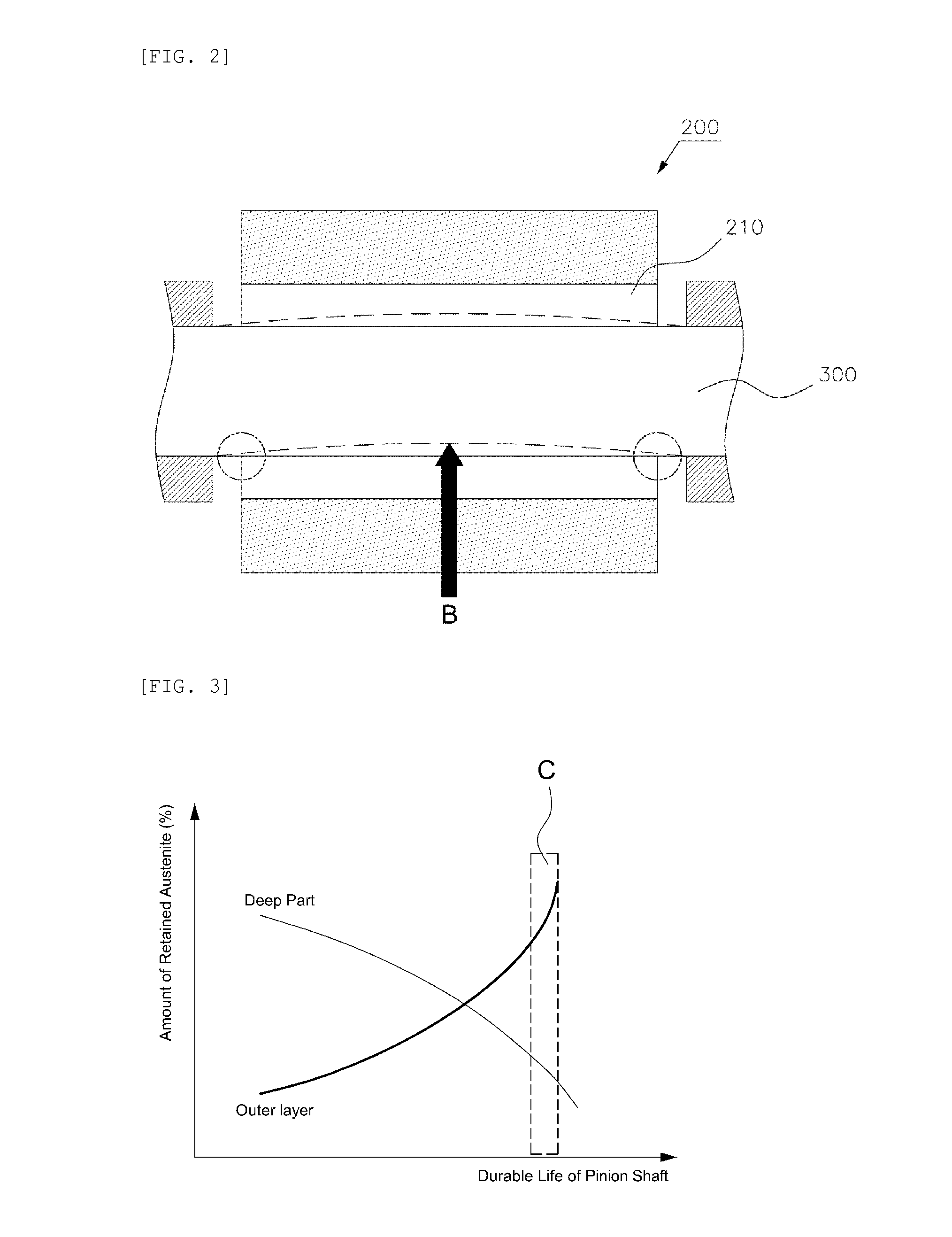
This is an unavoidable phenomenon as long as austenite exists in the material.
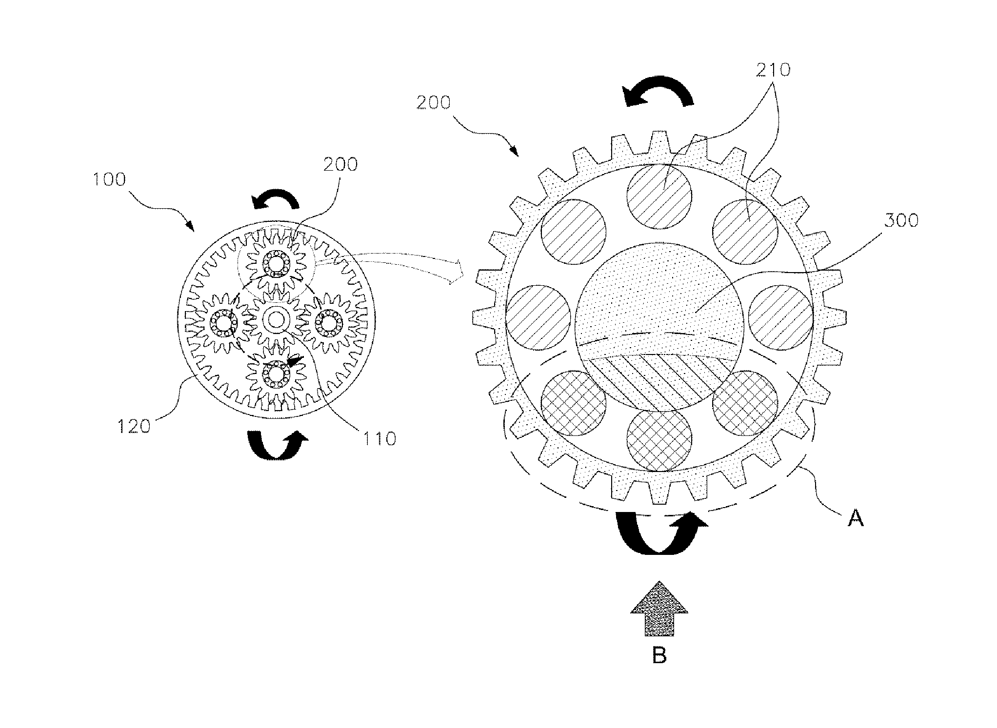
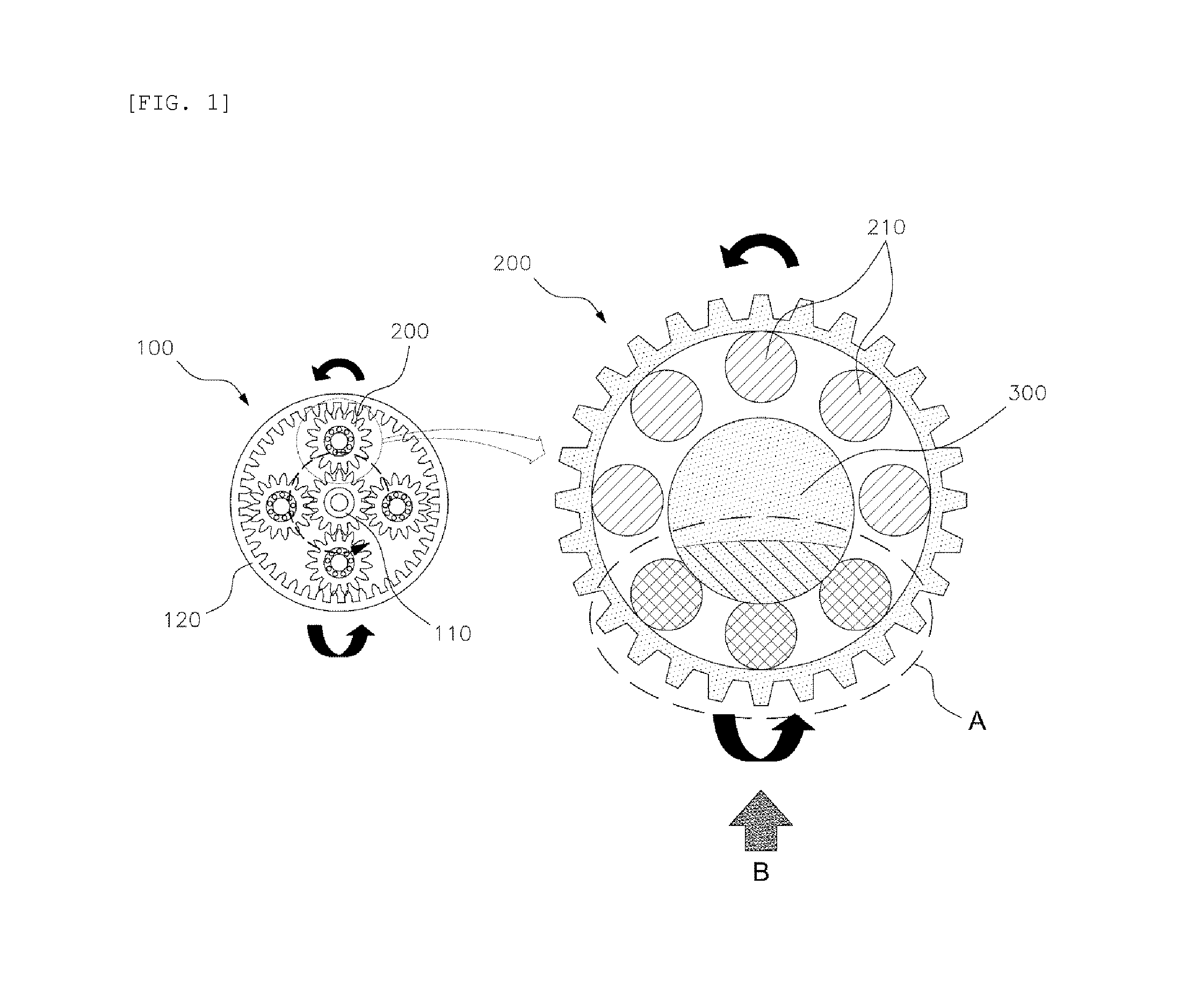
When the pinion shaft is bent, uneven contact between the needle bearing and the pinion shaft results in the generation of edge load.
This can result in damage to and peeling of the surface of the pinion shaft.
However, this method has problems of low productivity due to the complicated manufacturing processes, and further raises production costs.
However, the bearing steel which has been used for the pinion shaft does not satisfy these need.
However, this approach raises production costs due to the use of these expensive additive atoms.

Method used


Image

  • Long life pinion shaft and method for manufacturing thereof
  • Long life pinion shaft and method for manufacturing thereof
  • Long life pinion shaft and method for manufacturing thereof

Examples


Embodiment Construction

[0051]Hereinafter, the preferred embodiment of the present invention now will be described in detail with reference to the accompanying drawings.

[0052]It is understood that the term “vehicle” or “vehicular” or other similar term as used herein is inclusive of motor vehicles in general such as passenger automobiles including sports utility vehicles (SUV), buses, trucks, various commercial vehicles, watercraft including a variety of boats and ships, aircraft, and the like, and includes hybrid vehicles, electric vehicles, plug-in hybrid electric vehicles, hydrogen-powered vehicles and other alternative fuel vehicles (e.g. fuels derived from resources other than petroleum). As referred to herein, a hybrid vehicle is a vehicle that has two or more sources of power, for example both gasoline-powered and electric-powered vehicles.

[0053]The terminology used herein is for the purpose of describing particular embodiments only and is not intended to be limiting of the invention. As used herein...


PUM

PropertyMeasurementUnit
outer diameteraaaaaaaaaa
inner diameteraaaaaaaaaa
weightaaaaaaaaaa

Abstract

Disclosed is a long life pinion shaft having improved durability by forming an outer diameter portion thereof with high carbon alloy steel and the inner diameter portion medium carbon steel. In particular, the high carbon alloy steel, is selected from the group consisting of: high carbon chromium bearing steel; high speed tool steel; alloy tool steel; and / or carbon alloy steel.

Description

CROSS-REFERENCE TO RELATED APPLICATIONS[0001]This application claims priority under 35 U.S.C. §119 to Korean Patent Application No. 10-2012-72608, filed on Jul. 4, 2012, in the Korean Intellectual Property Office, the disclosure of which is incorporated herein by reference in its entirety.BACKGROUND OF THE INVENTION[0002]1. Field of the Invention[0003]The present invention relates to a pinion shaft and a method for manufacturing thereof, more particularly, to a pinion shaft inserted into the middle of a pinion gear and combined with a carrier. The pinion shaft has improved durability (“long life”), which is provided, in particular, by forming the outer diameter portion of the pinion shaft of a high carbon alloy steel comprising some additive atoms, and the inner diameter portion of the pinion shaft of a medium carbon steel.[0004]2. Description of the Related Art[0005]Planetary gears are generally a gear system comprising a pair of gears engaged with each other, such that each of the...

Claims


Application Information

Patent Timeline
Patent Type & Authority Applications(United States)
IPC IPC(8): B21C23/00
CPCF16C3/02B21C23/007B21C23/22B21C33/004B23K31/00C21D9/28C23C8/00F16H57/023
Inventor KANG, MIN-WOO
Owner HYUNDAI MOTOR CO LTD
Learn More