Electronic device
- Summary
- Abstract
- Description
- Claims
- Application Information
AI Technical Summary
Benefits of technology
Problems solved by technology
Method used
Image

Examples
Embodiment Construction
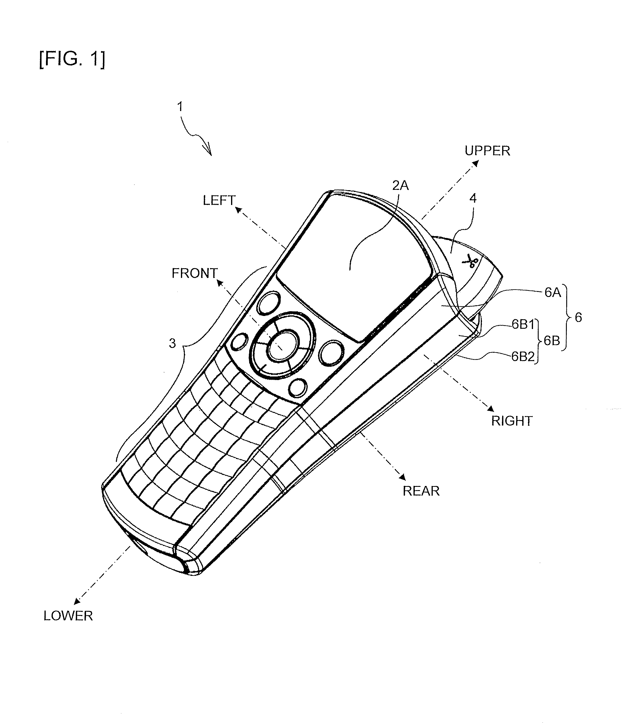
[0039]An embodiment of the present disclosure will be described below by referring to the attached drawings. In the following explanation, terms “front”, “rear”, “left”, “right”, “upper”, and “lower” refer to directions indicated in FIGS. 1 to 5.
[0040]
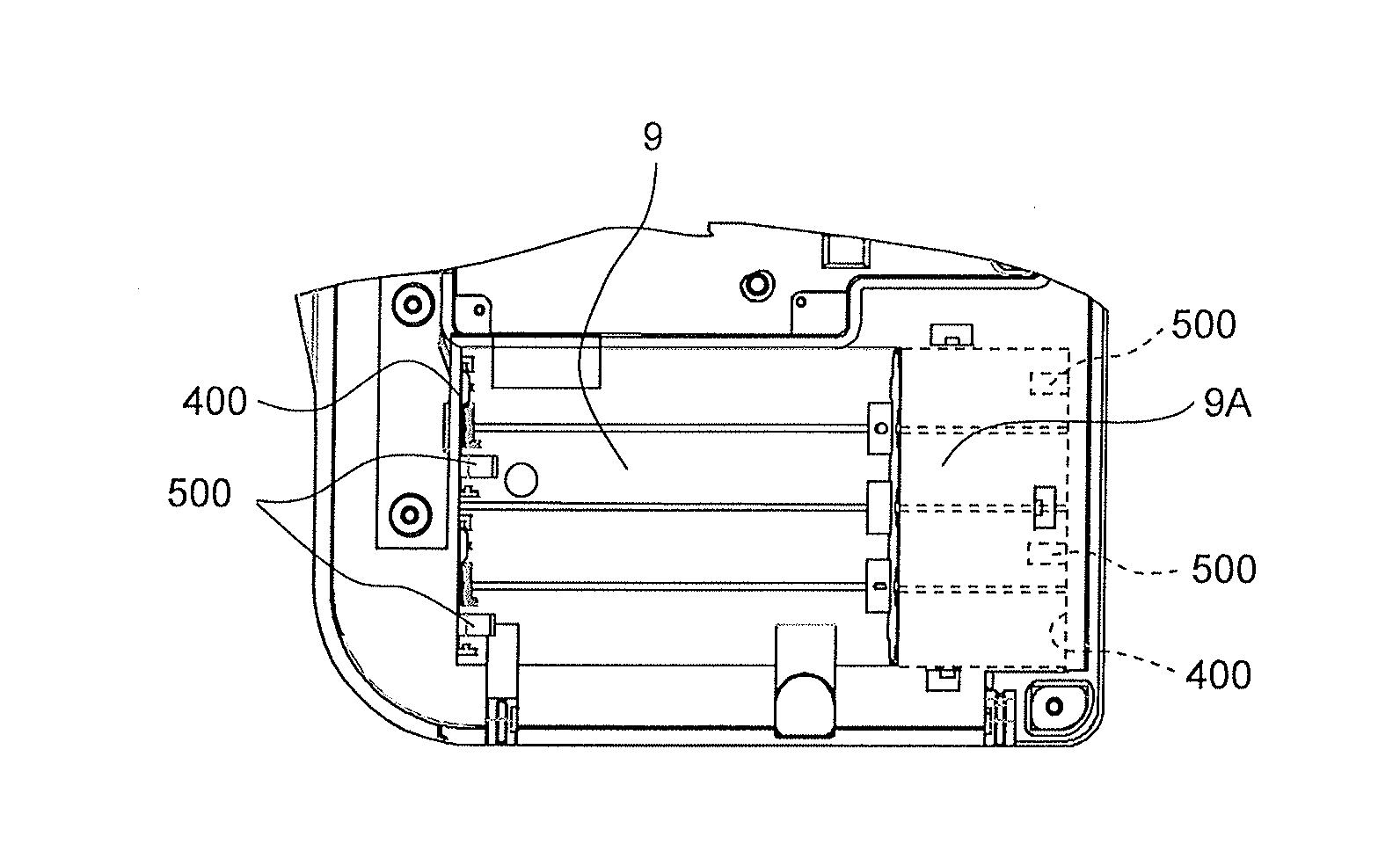
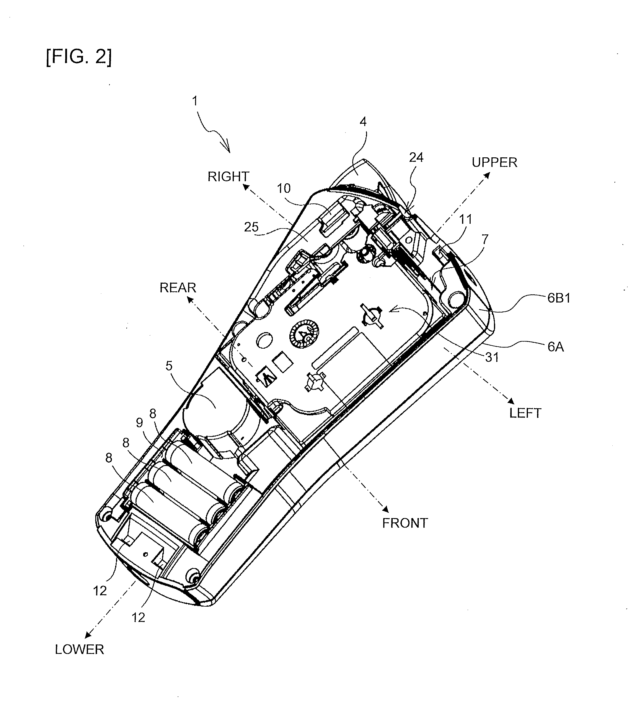
[0041]An entire configuration of a print label producing device 1 of the present embodiment will be described by using FIG. 1. As illustrated in FIG. 1, the print label producing device 1 is a handheld type print label producing device gripped by the hand of a user. A housing 6 of this print label producing device 1 includes a front cover 6A constituting a device front surface and a rear cover 6B constituting a device rear surface. Moreover, this rear cover 6B includes a rear cover body 6B1 incorporating various mechanisms and a detachable cover 6B2 capable of being removed from the rear cover body 6B1 when a cartridge 31 or a dry battery 8 is detached / attached.
[0042]On an upper side of the above described front cover 6A, a liquid crys...
PUM
 Abstract
Description
Claims
Application Information