Multiaxial hinge module and electronic device
- Summary
- Abstract
- Description
- Claims
- Application Information
AI Technical Summary
Benefits of technology
Problems solved by technology
Method used
Image

Examples
Embodiment Construction
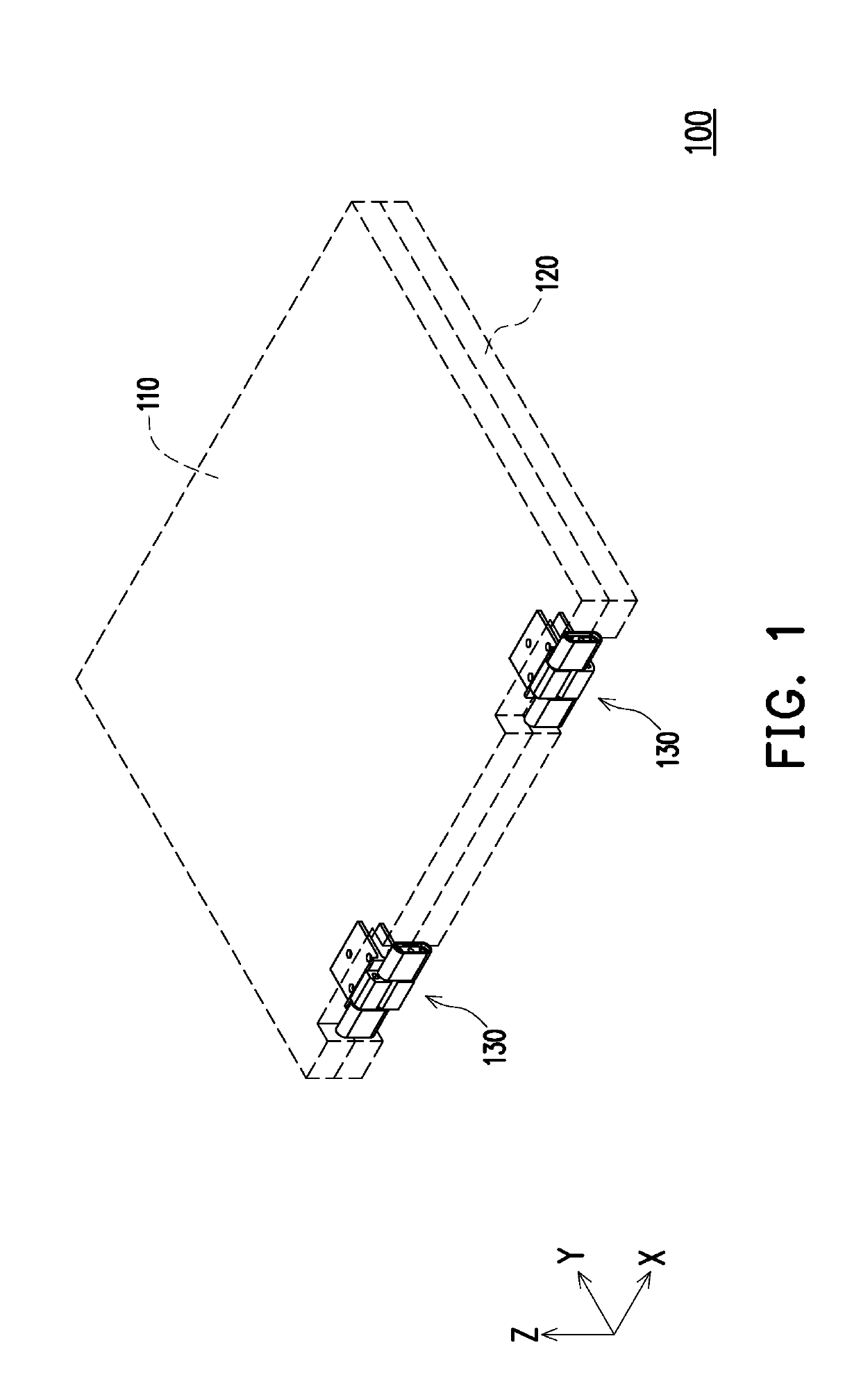
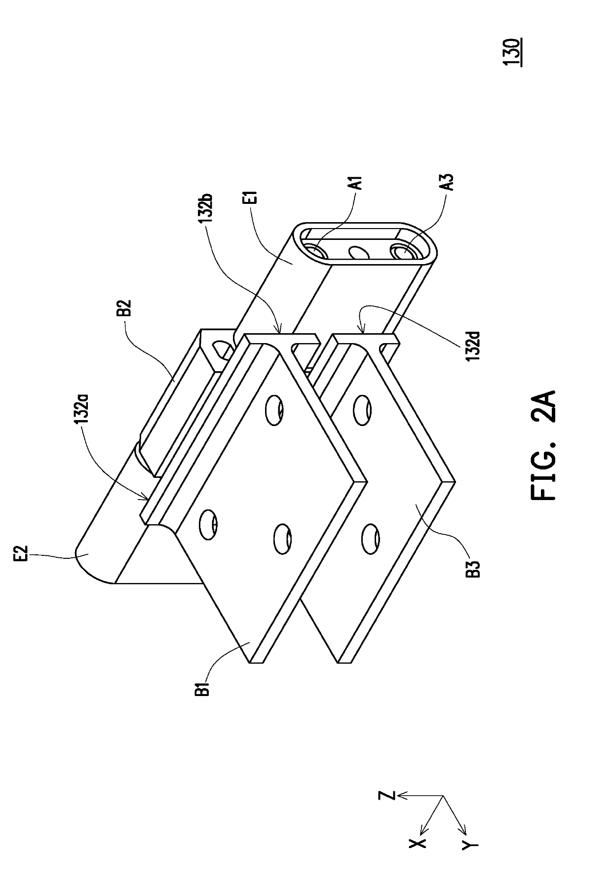
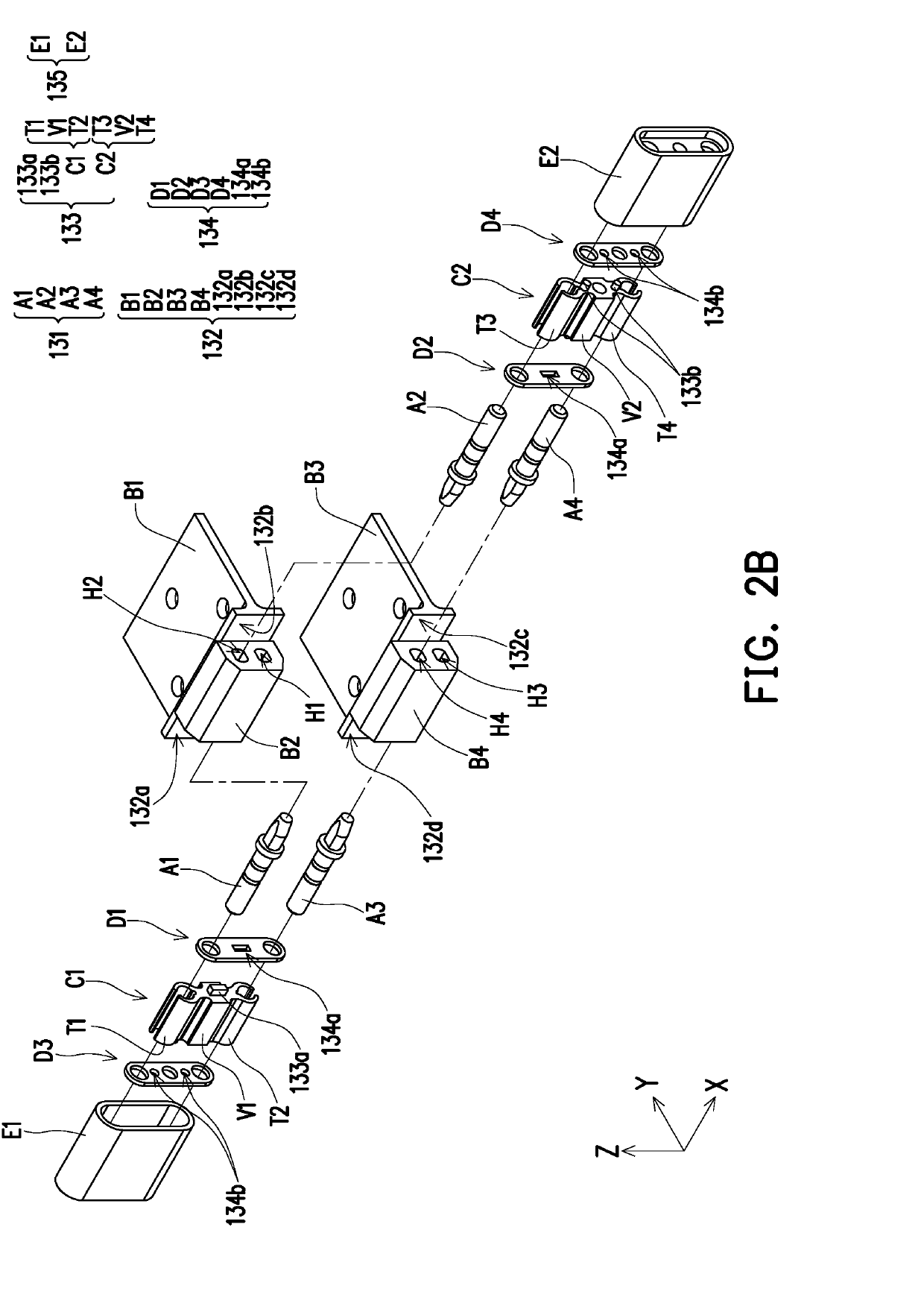
[0021]FIG. 1 is a schematic diagram of an electronic device according to an embodiment of the invention. FIG. 2A is a schematic diagram of a multiaxial hinge module of FIG. 1. A Cartesian coordinate system X-Y-Z is provided here for easier component descriptions. Please refer to FIG. 1 and FIG. 2A at the same time. In this embodiment, an electronic device 100 is, for example, a notebook computer, which includes a first body 110 (for example, a display screen), a second body 120 (for example, a system host), and at least one multiaxial hinge module 130. Two multiaxial hinge modules 130 are illustrated as an example of this embodiment, and the two multiaxial hinge modules 130 are in symmetrical configuration relative to the centerline of the first body 110 or the second body 120. The multiaxial hinge module 130 is connected to the same side of the first body 110 and the second body 120, and the two multiaxial hinge modules 130 are independent from each other. The first body 110 and th...
PUM
 Abstract
Description
Claims
Application Information