Power unit for vehicle

a technology for power units and vehicles, applied in the field of power units for vehicles, can solve the problems of submergence affecting the speed change actuator disposed below, and achieve the effects of preventing the occurrence of submergence, reducing the risk of submergence, and improving the compactness of the power uni

Active Publication Date: 2014-10-02
HONDA MOTOR CO LTD
View PDF9 Cites 9 Cited by
  • Summary
  • Abstract
  • Description
  • Claims
  • Application Information

AI Technical Summary

Benefits of technology

[0013]According to certain embodiments of the present invention, the speed change actuator is disposed in the position such that the transmission disposed below the inclined cylinder axis is interposed between the speed change actuator and the crankshaft. As viewed from the axial direction of the crankshaft, the speed change actuator is disposed at a position equal to that of the crankshaft. Thus, the speed change actuator can be prevented from being affected by submergence. In addition, the exhaust pipe connected to the lower side wall of the cylinder head is extended so as to pass above the transmission and partly overlap the upper portion of the speed change actuator as viewed from the axial direction of the crankshaft. Thus, a space for disposing the exhaust pipe can also be secured.
[0014]In addition, according to certain embodiments of the present invention, the axis of rotation of the upper gear group of the driving gear group and the driven gear group forming the transmission is disposed at the same height as the axis of the crankshaft. The speed change actuator is disposed on the outside on the opposite side of the upper gear group from the crankshaft. The output shaft is disposed below the lower gear group. Thus, a space for disposing the output shaft can be secured easily, and the power unit can be made more compact.
[0015]According to certain embodiments of the present invention, the oil storage tank is disposed outward in the axial direction of the crankshaft on the periphery of the clutch actuator. Thus, oil can be stored and retained at a relatively high position. This, coupled with the arrangement of the clutch actuator and the speed change actuator at a relatively high position, makes it possible to reduce a downward bulge of the power unit and, thus, increase a ground clearance of the vehicle.
[0016]According to certain embodiments of the present invention, the oil filter is disposed in the oil storage tank at a height equal to that of the crankshaft. Thus, the power unit can be miniaturized while the oil filter is prevented from being affected by submergence.
[0017]According to certain embodiments of the present invention, the oil cooler is disposed on the upper portion of the oil storage tank. Thus, the power unit can be miniaturized while maintainability is improved by disposing accessories on one side along the axis of the crankshaft in a concentrated manner.
[0018]Further, according to certain embodiments of the present invention, the generator cover and the reduction mechanism cover are attached to the engine main body on the opposite side from the oil storage tank in the direction along the axis of the crankshaft. Thus, bulges from the engine main body are balanced on both sides of the crankshaft, so that mountability in the vehicle can be improved.

Problems solved by technology

However, the speed change actuator disposed below may be affected by submergence.

Method used


Image

  • Power unit for vehicle
  • Power unit for vehicle
  • Power unit for vehicle

Examples


Embodiment Construction

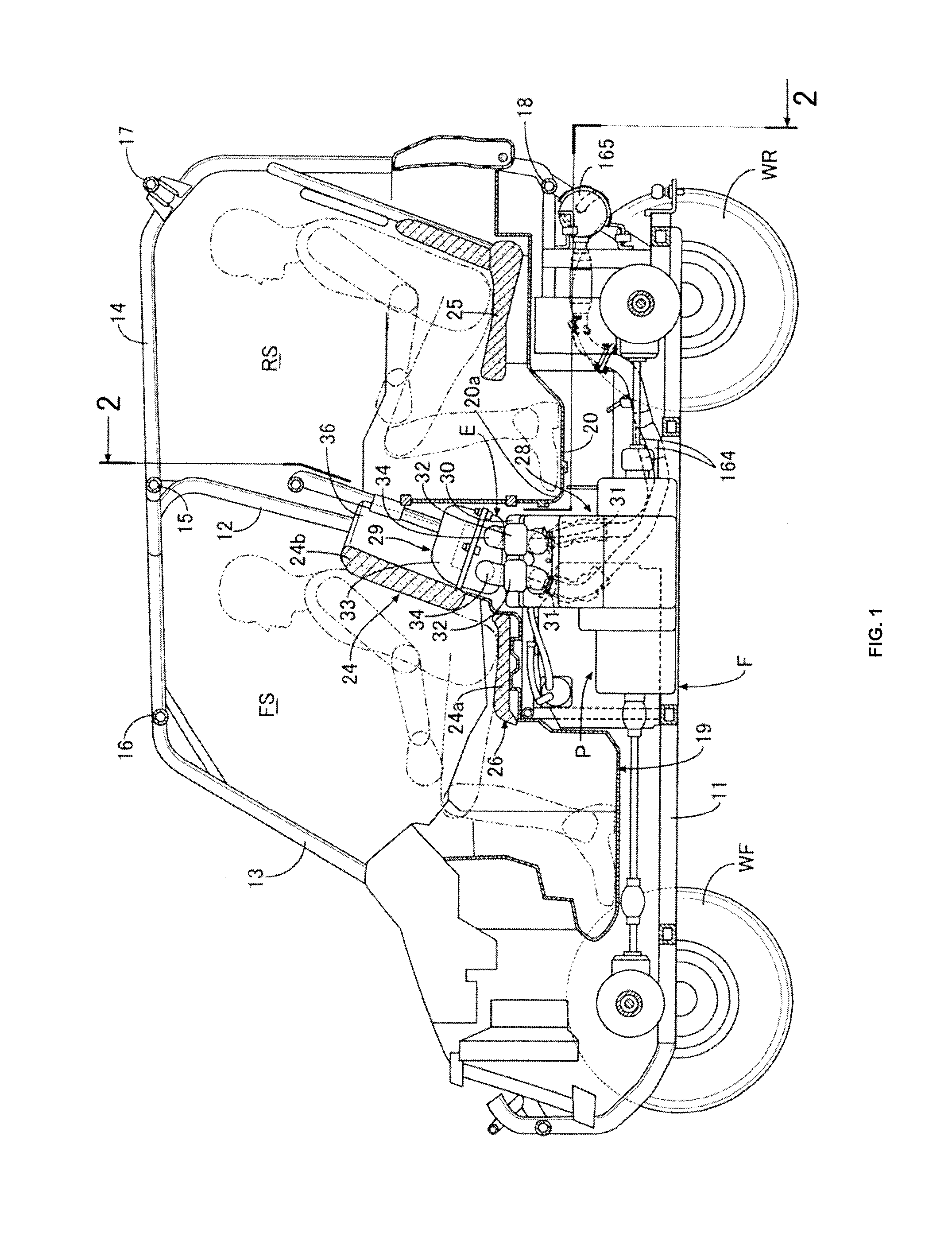
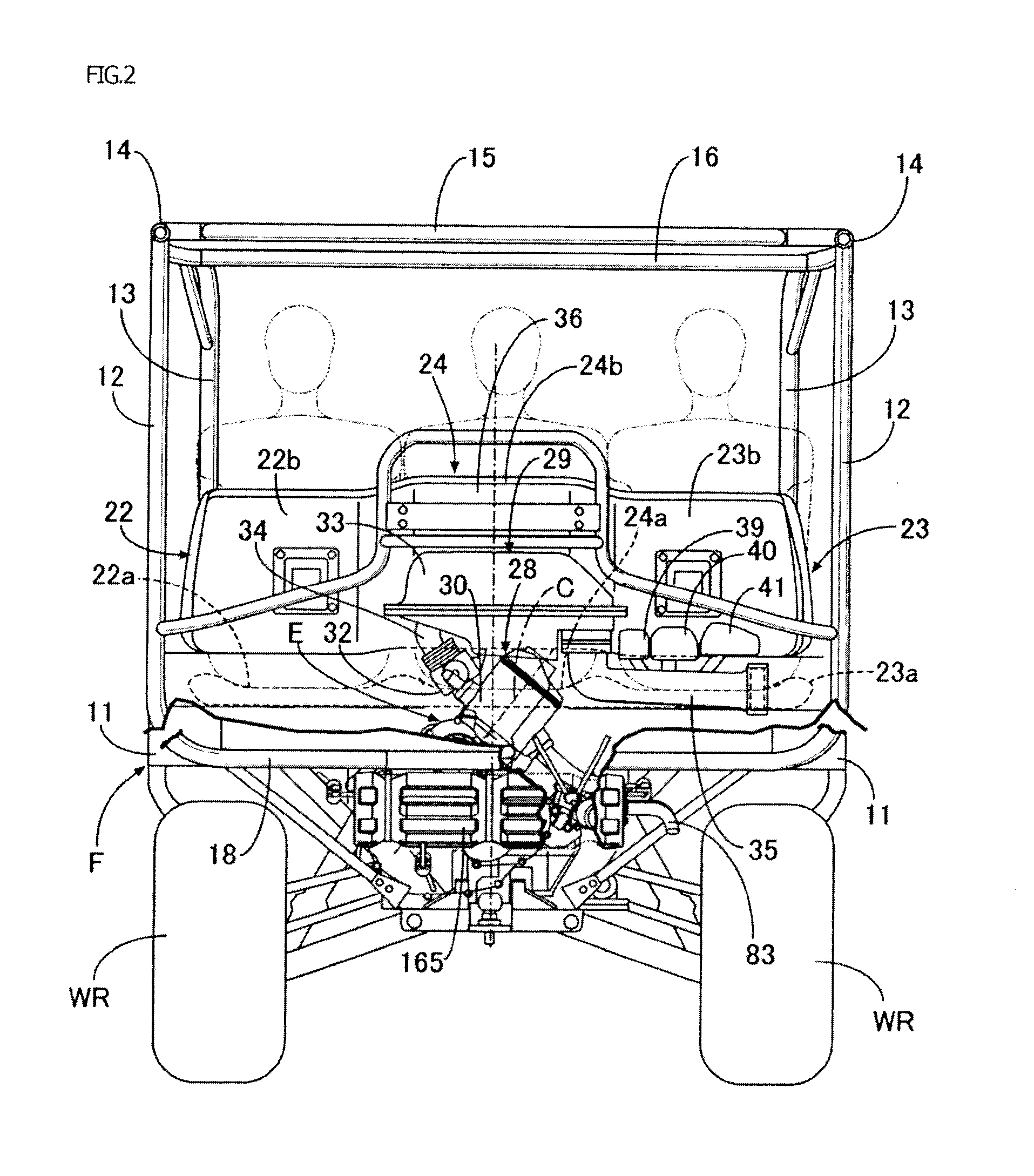
[0031]Certain embodiments of the present invention will be described with reference to the accompanying FIGS. 1 to 12. In the following description, the terms “front,”“rear,”“left,”“right,”“up,” and “down” refer to directions viewed from an occupant riding in a four-wheeled vehicle.

[0032]First, in FIG. 1 and FIG. 2, a pair of left and right front wheels WF is suspended from a front portion of a vehicle body frame F of an off-road travelling four-wheeled vehicle, and a pair of left and right rear wheels WR is suspended from a rear portion of the vehicle body frame F.

[0033]The vehicle body frame F include a pair of left and right lower frames 11 extending in a forward-rearward direction. The vehicle body frame F also includes a pair of left and right center upright frames 12 rising upward from intermediate portions in the forward-rearward direction of the lower frames 11. The vehicle body frame F further includes a pair of left and right front side frames 13 extending frontward from u...


PUM


Abstract

A transmission partly overlapping clutches as viewed from an axial direction of a crankshaft is disposed below an inclined cylinder axis of an engine main body. A speed change actuator is disposed in a position such that the transmission is interposed between the speed change actuator and the crankshaft. An exhaust pipe connected to a lower side wall of a cylinder head is extended so as to pass above the transmission and partly overlap an upper portion of the speed change actuator as viewed from the axial direction of the crankshaft.

Description

BACKGROUND[0001]1. Field[0002]Certain embodiments of the present invention relate to a power unit for a vehicle. The power unit includes a clutch and a transmission disposed midway in a power transmission system between a crankshaft and a driving wheel. The clutch and transmission are housed in an engine main body that rotatably supports the crankshaft. A speed change actuator for switching the speed change stage of the transmission is disposed on the engine main body.[0003]2. Description of the Related Art[0004]Such a power unit for a vehicle is known in Japanese Patent Laid-Open No. 2008-82209 (Patent Document 1) and the like.SUMMARY[0005]In the power unit disclosed in the above Patent Document 1, a clutch actuator and a speed change actuator disposed below the clutch actuator are disposed on an engine main body whose cylinder axis is inclined. However, the speed change actuator disposed below may be affected by submergence. Accordingly, the speed change actuator is desired to be ...

Claims


Application Information

Patent Timeline
Patent Type & Authority Applications(United States)
IPC IPC(8): B60W10/06B60W10/02B60W10/11
CPCB60W10/06B60W10/11B60W2510/02B60W2510/06B60W10/02B60Y2304/01B60Y2400/428F16H61/0009B60K5/02B60K13/02B60K17/34B60K2005/003B60Y2200/20B60K5/04B60K13/04B60K17/02B60K17/08F16H2057/0203
Inventor NORITA, KAZUHIROMITSUBORI, TOSHIMASA
Owner HONDA MOTOR CO LTD
Why Eureka
Try Eureka