
Ink jet printing apparatus and print head temperature control method

a printing apparatus and temperature control technology, applied in printing, other printing apparatus, etc., can solve the problems of high head temperature, easy to reach a higher temperature, and relatively large decrease in head temperatur

Active Publication Date: 2014-10-09
CANON KK
View PDF0 Cites 0 Cited by
  • Summary
  • Abstract
  • Description
  • Claims
  • Application Information

AI Technical Summary

Benefits of technology

This approach maintains print head temperatures within a suitable range, reducing density variations and preventing excessive temperature rises or drops, thereby enhancing the consistency of printed images.

Problems solved by technology

However, problems such as those described below often arise in the prior art temperature controls described in the above two publications.
Therefore, for example, when the head temperature rises due to a scan in which high density images are printed, that is, images with a high ejection frequency, control is carried out with the raised temperature at the time of scan completion as the target and as such the head temperature is prone to reach a higher temperature.
Subsequently, when there is a print interruption due to, for example, print data transmission waiting time, the head temperature has a relatively large decrease due to the cessation of the ejection operation.
Therefore, in the case where density of an image to be printed is low and thus the head temperature is lowered a comparatively large amount during scan, the difference between the lowered head temperature at the time when the scan is completed and the head temperature at the start of the next scan, which is obtained by heating the print head to the stable ejection temperature, becomes large, and a large density difference occurs between the images of the scans.
Therefore, also in the case where the print density is high the difference between the head temperature at the time of scan start and the head temperature at the time of scan completion is large, and density variation in the image is prone to occur.
The ejection frequency increases due to the printing of an image with a high print density, and such scan raises the head temperature.
As a result, in these head temperature controls there is a problem wherein head temperature variation is prone to become large.

Method used


Image

  • Ink jet printing apparatus and print head temperature control method
  • Ink jet printing apparatus and print head temperature control method
  • Ink jet printing apparatus and print head temperature control method

Examples


first embodiment

[0037]FIGS. 3A and 3B are flowcharts that illustrate the print head temperature control of a first embodiment of the present invention.

[0038]First, as shown in FIG. 3A, when one print head scan has been completed, at step 301 the head temperature control of the present embodiment acquires Tfinish, the head temperature at the print completion time.

[0039]Next, when there is a print scan start command relating to the next scan, the process shown in FIG. 3B is initiated, and first at step 401 Tstart, the head temperature at the time of print scan start, is acquired. Next, at step 402, it is determined if Tfinish, the acquired head temperature at the print scan completion time, is at or below Tstable, the stable ejection temperature of the print head of the present embodiment (at or below the first prescribed temperature). The stable ejection temperature Tstable is dependent on the structure of the print head, the type of ink, and the like, and is the temperature at which ink ejection is...

second embodiment

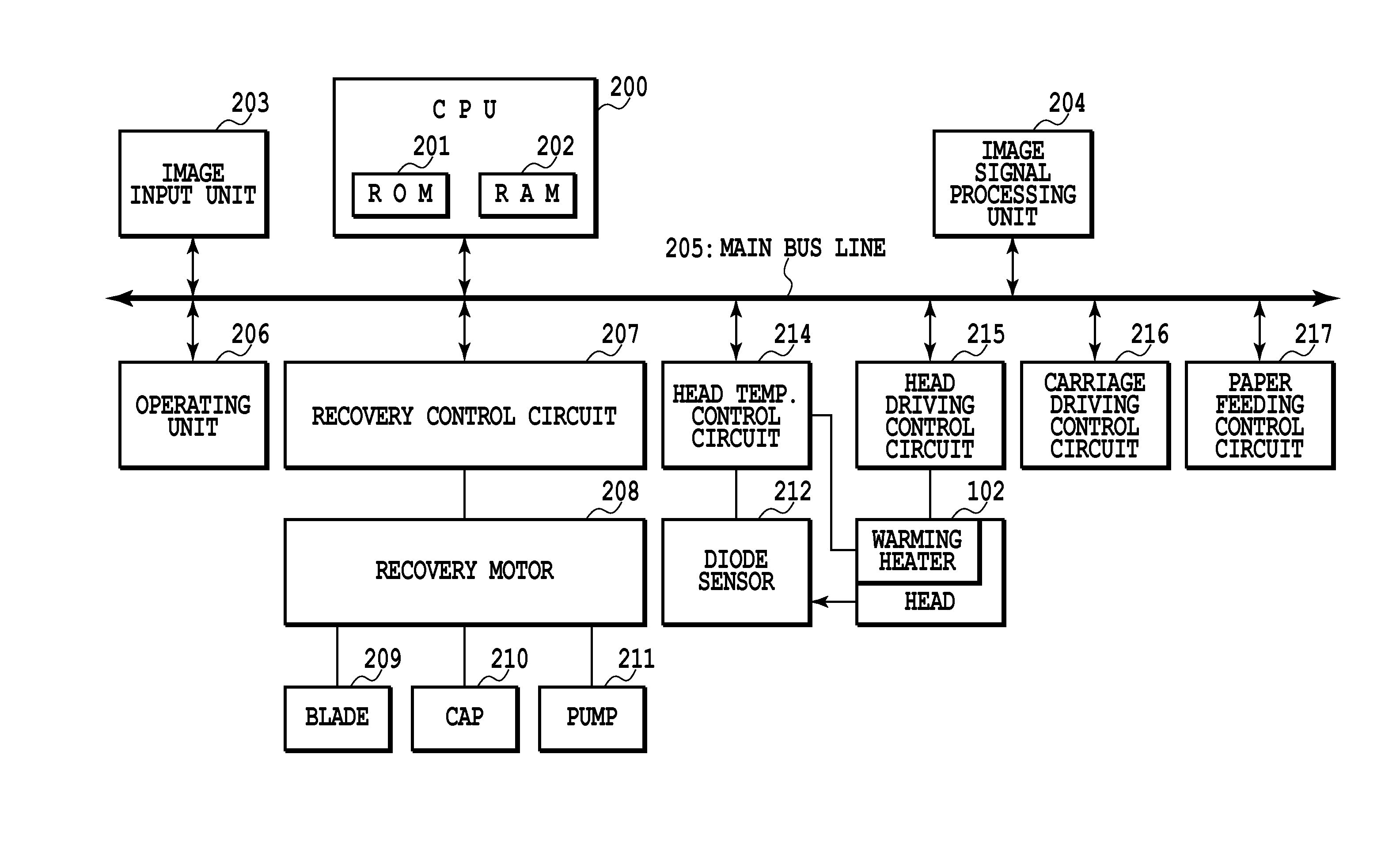
[0058]In the first embodiment described above the target temperature was made to depend on the head temperature at the time of print scan completion. In contrast, in the second embodiment of the present invention, the target temperature is obtained by counting the number of print dots in one scan, and according to that value determining whether to add to or subtract the prescribed temperature ΔT from the head temperature at the time of print scan completion. That is, print dot count is information that relates to the print head temperature, and is the sum of the number of ink drops ejected in one scan of the print head from the plurality of ejection openings disposed on the print head. In other words, it is the sum of the number of ejections and corresponds to the ejection frequency of 1 scan. Thus this dot count unit is equivalent to the temperature information collection unit.

[0059]FIGS. 5A and 5B are flowcharts that illustrate print head temperature control according to a second ...

third embodiment

[0069]In a third embodiment of the present invention, in addition to the temperature control of the first embodiment, the print head is heated raising the temperature to the stable ejection temperature before carrying out printing on a new print medium. A fixed amount of time, due to paper ejection, feeding, etc., is commonly required to start printing on a new print medium subsequent to the completion of printing on 1 sheet of a print medium. Therefore the head temperature often drops according to the relationship among the ambient temperature and the length of time until commencing printing on the new print medium.

[0070]FIG. 6 is a flowchart illustrating the head temperature control executed when a new print medium is fed, in accordance with a third embodiment of the present invention.

[0071]When print medium feeding is executed the present process is initiated, Tstart, the head temperature at the time of print scan start is first acquired at step 901. Next, at step 902, it is dete...


PUM


Abstract

When the head temperature Tfinish, which is the head temperature at the time of completion of a preceding scan, is higher than the stable ejection temperature Tstable, the target temperature is made a temperature that is only a temperature value ΔT lower than the head temperature Tfinish. On the other hand, when Tfinish, the head temperature at the time of print completion, is lower than the stable ejection temperature Tstable, the target temperature is made a temperature that is only a temperature value ΔT higher than the head temperature Tfinish. Because of this it is possible to inhibit head temperature rise in the case where an image with a high print density is printed.

Description

BACKGROUND OF THE INVENTION[0001]1. Field of the Invention[0002]The present invention relates to an ink jet printing apparatus and method for controlling print head temperature, and particularly to a configuration for controlling the temperature of ink ejecting print heads, i.e. the temperature of ejected ink.[0003]2. Description of the Related Art[0004]Traditionally, control of the temperature of the ink in the print head has been carried out to control the variation of the volume of an ejected ink drop with respect to ink jet printing apparatuses. This can inhibit the occurrence of density variation in printed images. On the other hand, the temperature of the ink in the print head (also simply referred to herein as the temperature of the print head or the head temperature) changes in accordance with the ejection frequency of the ink and the ejection rest interval. For example, when an interruption of the printing operation (for example, a recovery operation or waiting for print da...

Claims


Application Information

Patent Timeline
Patent Type & Authority Applications(United States)
IPC IPC(8): B41J2/07
CPCB41J2/04563B41J2/072B41J2/0458B41J2/0454
Inventor OONUKI, KENICHIKANDA, HIDEHIKOMARU, AKIKOYOSHIKAWA, HIROKAZUTAIRA, HIROSHI
Owner CANON KK
Learn More