
Organic light-emitting display device

a display device and organic technology, applied in semiconductor devices, lighting and heating apparatus, instruments, etc., can solve the problems of affecting the reliability of the device, and affecting the uniform width of the seal pattern, so as to reduce the variation in density, improve the reliability of the device, and reduce the effect of variation in density

Active Publication Date: 2020-03-17
LG DISPLAY CO LTD
View PDF7 Cites 1 Cited by
  • Summary
  • Abstract
  • Description
  • Claims
  • Application Information

AI Technical Summary

Benefits of technology

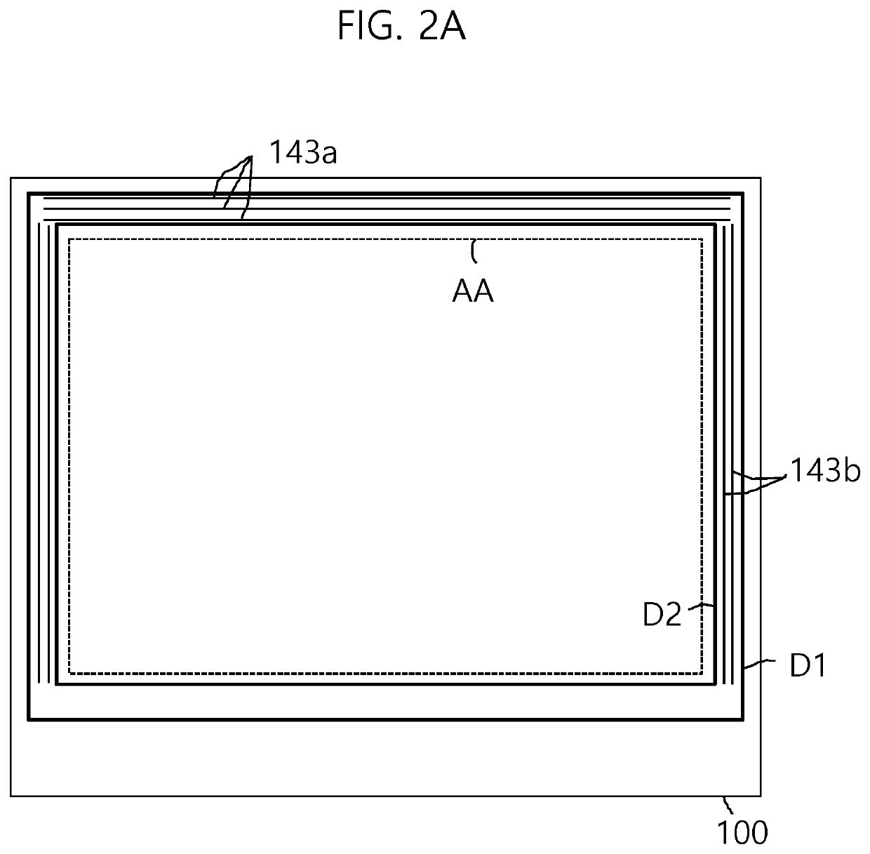
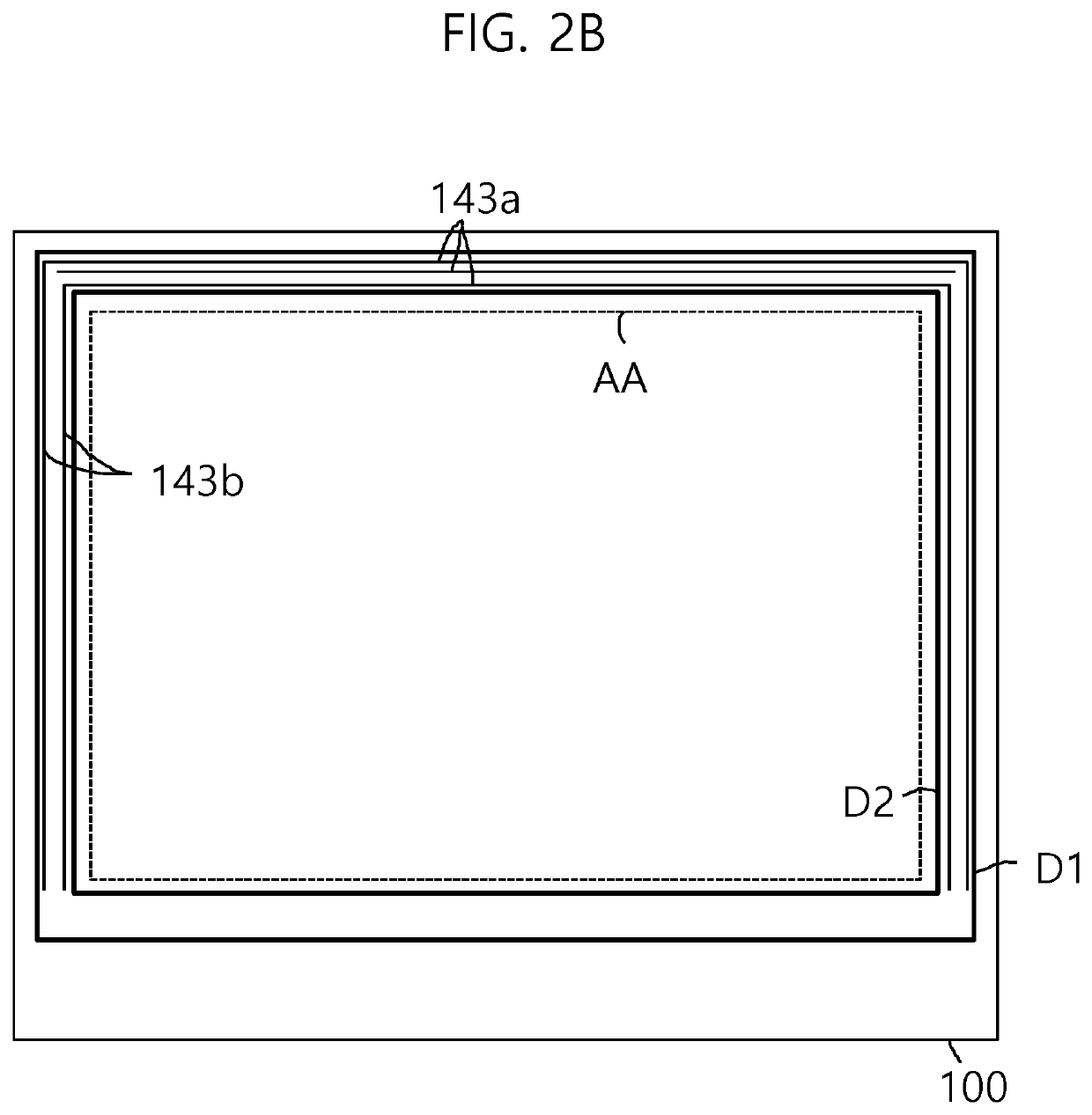
[0013]In some embodiments, the present disclosure provides an organic light-emitting display device, in which a compensation pattern is selectively provided between two dam patterns depending on the arrangement density of a lower structure thereof, thereby making the width of a seal pattern uniform for each area and consequently improving the reliability of the device.
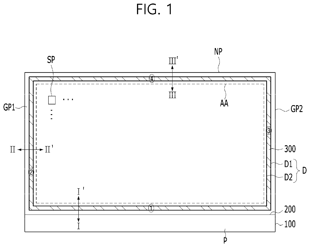
[0015]To achieve these objects and other advantages and in accordance with the purpose of the disclosure, as embodied and broadly described herein, an organic light-emitting display device includes a substrate including an active area having a plurality of sub-pixels and a non-active area formed around a periphery of the active area, the non-active area including a pad portion at a first side, gate-driving portions at second and third sides that are contiguous to respective ends of the first side, and a non-pad portion at a fourth side that faces the first side and is located between the gate-driving portions at the second and third sides, an encapsulation substrate disposed to face the substrate, a first dam pattern and a second dam pattern spaced apart from each other in the non-active area of each of the first to fourth sides, each of the first dam pattern and the second dam pattern being formed in a closed-loop configuration, a seal pattern located between the first dam pattern and the second dam pattern and located between the substrate and the encapsulation substrate, and a first compensation pattern in the non-active area of the fourth side, the seal pattern covering the first compensation pattern. Embodiments provided herein may therefore compensate for surface deviation of the substrate among the non-active areas of the first to fourth sides.
[0016]Through this configuration, the organic light-emitting display device of the present disclosure is capable of minimizing variation in density (i.e., variations of the mass per unit volume) among the areas on the top surface of the substrate that overlap the seal pattern, thereby making the width of the seal pattern uniform for each area. As a result, the reliability of the device may be improved.

Problems solved by technology

Therefore, an area in which the seal pattern is formed relatively thin is vulnerable to permeation of external air or moisture in the lateral direction.
Further, the difference in width of the seal patterns formed in the respective areas accelerates the deterioration of the vulnerable area over time, thereby degrading the reliability of the device.

Method used


Image

  • Organic light-emitting display device
  • Organic light-emitting display device
  • Organic light-emitting display device

Examples


Embodiment Construction

[0026]The advantages and features of the present disclosure and the way of attaining them will become apparent with reference to embodiments described below in detail in conjunction with the accompanying drawings. The present disclosure, however, is not limited to the embodiments disclosed hereinafter, and may be embodied in many different forms. Rather, these exemplary embodiments are provided so that this disclosure will be thorough and complete and will fully convey the scope to those skilled in the art. The scope of the present disclosure should be defined by the claims.

[0027]In the drawings for explaining the exemplary embodiments of the present disclosure, the illustrated shape, size, ratio, angle, and number are given by way of example, and thus are not limited to the disclosure of the present disclosure. Throughout the present specification, the same reference numerals designate the same constituent elements. In addition, in the following description of the present disclosur...


PUM

PropertyMeasurementUnit
thicknessaaaaaaaaaa
thicknessaaaaaaaaaa
thicknessaaaaaaaaaa

Abstract

Disclosed is an organic light-emitting display device, in which a compensation pattern is selectively provided between two dam patterns depending on the arrangement density of a lower structure thereof, thereby making the width of a seal pattern uniform for each area. As a result, the reliability of the device is greatly improved.

Description

CROSS-REFERENCE TO RELATED APPLICATION(S)[0001]This application claims the benefit of Korean Patent Application No. 10-2017-0105028, filed on Aug. 18, 2017, which is hereby incorporated by reference as if fully set forth herein.BACKGROUND[0002]Technical Field[0003]The present disclosure relates to an organic light-emitting display device, and more particularly to an organic light-emitting display device, in which a compensation pattern is selectively provided between two dam patterns depending on the arrangement density of a lower structure thereof, thereby improving the reliability of the device.[0004]Description of the Related Art[0005]Recently, with the arrival of the information age, the field of displays for visually displaying electrically conveyed information signals has developed rapidly. In response to this, various kinds of flat panel display devices having excellent characteristics, such as a small thickness, a low weight, and low power consumption, have been developed an...

Claims


Application Information

Patent Timeline
Patent Type & Authority Patents(United States)
IPC IPC(8): H01L27/32G09G3/3225H01L51/52H01L51/10G09G3/3275F21Y115/15
CPCH01L27/3276H01L51/5246G09G3/3275H01L27/3246G09G3/3225H01L51/105H01L27/3262H01L51/5237H01L51/5253G09G2300/0819H01L27/322H01L27/3258F21Y2115/15H01L51/5259H10K59/12H10K50/84H10K59/38H10K59/122H10K59/124H10K50/846H10K50/8426H10K50/844H10K59/35H10K59/1213H10K50/841H10K50/865H10K10/84H10K59/131
Inventor KIM, KI-DONG
Owner LG DISPLAY CO LTD
Learn More