
Light-emitting diode and light-emitting module

a technology of light-emitting modules and diodes, which is applied in the direction of basic electric elements, electrical apparatus, and semiconductor devices, can solve the problems of not meeting the requirements in practical applications, and achieve the effect of improving the stability of the spectrum waveform of the white light spectrum

Active Publication Date: 2022-08-23
KAISTAR LIGHTING (XIAMEN) CO LTD
View PDF35 Cites 0 Cited by
  • Summary
  • Abstract
  • Description
  • Claims
  • Application Information

AI Technical Summary

Benefits of technology

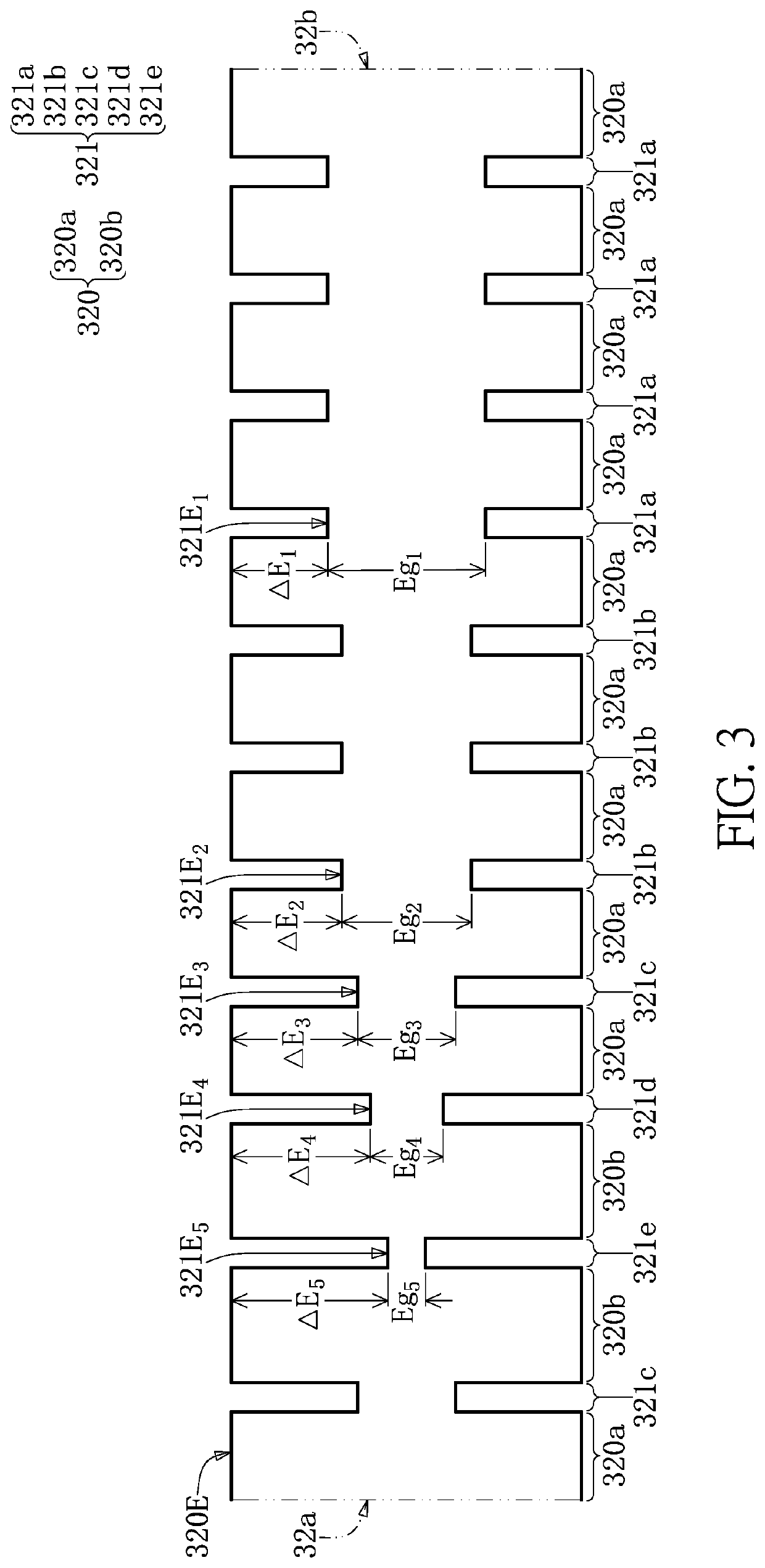
The present disclosure provides a light-emitting diode and module that can optimize the spectrum waveform of White light at the blue light wavelength band and improve its stability when the operating current is changed. This is achieved by using a light-emitting structure with multiple well layers and barrier layers that generate light beams with different wavelengths. The resulting blue light spectrum has a better stability even when the operating current density is changed.

Problems solved by technology

Furthermore, when a current for driving the blue light-emitting diode is varied, the white light spectrum that is generated by the blue light-emitting diode and the phosphor may fluctuate too much in the blue light wavelength band, which causes changing of various indicators of the color rendering index, and then may fail to satisfy the requirements in practical applications.

Method used


Image

  • Light-emitting diode and light-emitting module
  • Light-emitting diode and light-emitting module
  • Light-emitting diode and light-emitting module

Examples


first embodiment

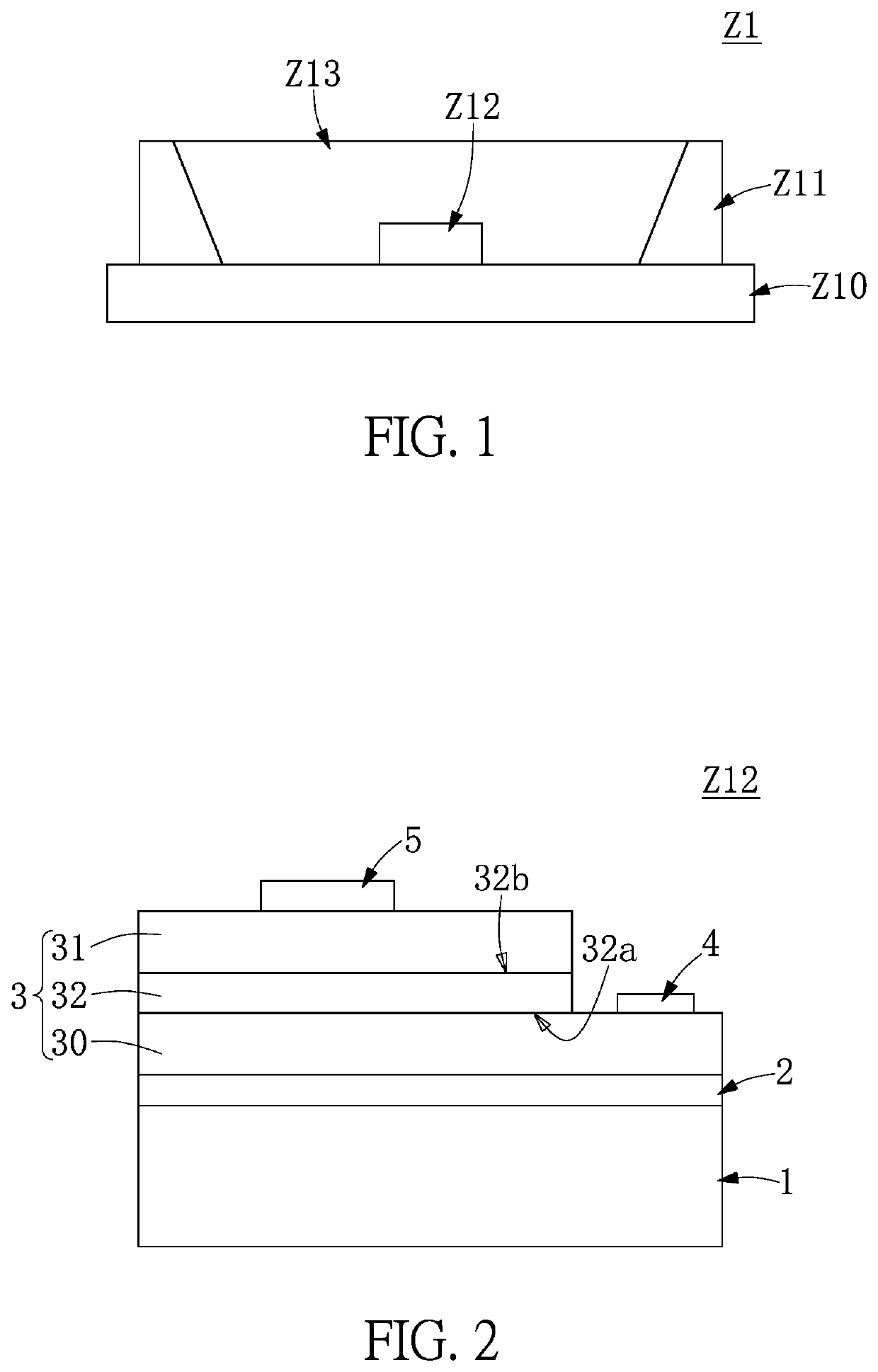
[0039]Reference is made to FIG. 1, which is a schematic cross-sectional view of a light-emitting module according to an embodiment of the present disclosure. In the instant embodiment, the light-emitting module Z1 is used to generate white light. As shown in FIG. 1, the light-emitting module Z1 includes a substrate Z10, a reflective assembly Z11, a light-emitting diode Z12, and a wavelength conversion layer Z13. The substrate Z10 has a die-bonding area defined thereon. In an embodiment, the material of the substrate Z10 can be made of a material having a high thermal conductivity, and a high reflectivity and a low transmittance for visible light, such as metal or ceramic. In another embodiment, the substrate Z10 can include a high thermally conductive base and a reflective layer coated thereon. The material of the substrate Z10 is not limited to being a single or composite material in the present disclosure.

[0040]The reflective assembly Z11 and the light-emitting diode Z12 are joint...


PUM

PropertyMeasurementUnit
FWHMaaaaaaaaaa
wavelengthaaaaaaaaaa

Abstract

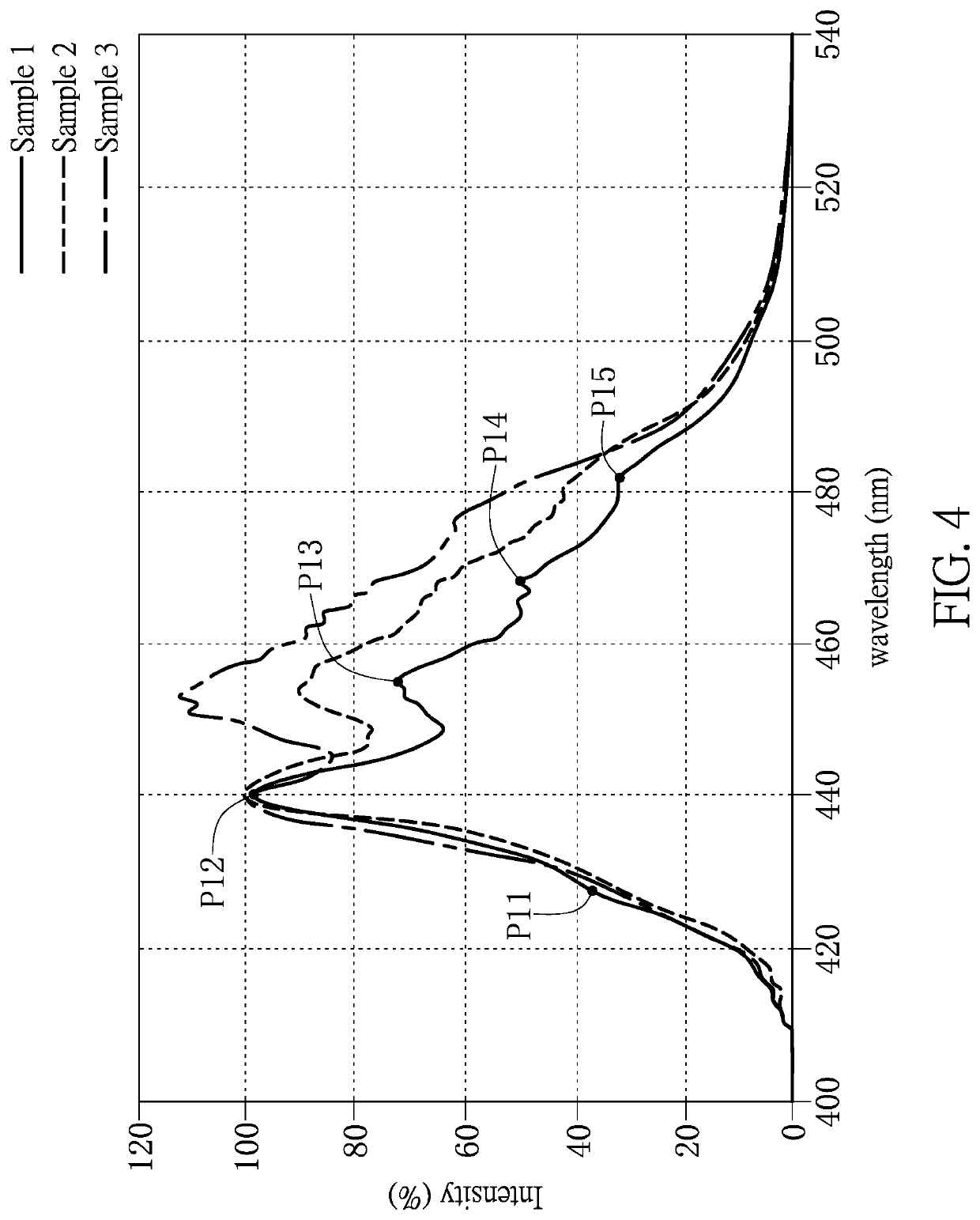
A light-emitting module and a light-emitting diode are provided. The light-emitting diode includes an epitaxial light-emitting structure to generate a light beam with a broadband blue spectrum. A spectrum waveform of the broadband blue spectrum has a full width at half maximum (FWHM) larger than or equal to 30 nm. The spectrum waveform has a plurality of peak inflection points, and a difference between two wavelength values to which any two adjacent ones of the peak inflection points respectively correspond is less than or equal to 18 nm.

Description

CROSS-REFERENCE TO RELATED PATENT APPLICATION[0001]This application claims the benefit of priority to China Patent Application No. 202010442369.3, filed on May 22, 2020 in People's Republic of China and. The entire content of the above identified application is incorporated herein by reference.[0002]This application is a continuation-in-part application of International Patent Application No. PCT / CN2019 / 117645, with an international filing date of Nov. 12, 2019, which has entered the United States in the national phase as U.S. application Ser. No. 16 / 629,367, and which is incorporated by reference herein in its entirety.[0003]Some references, which may include patents, patent applications and various publications, may be cited and discussed in the description of this disclosure. The citation and / or discussion of such references is provided merely to clarify the description of the present disclosure and is not an admission that any such reference is “prior art” to the disclosure desc...

Claims


Application Information

Patent Timeline
Patent Type & Authority Patents(United States)
IPC IPC(8): H01L33/50H01L33/08H01L33/06
CPCH01L33/504H01L33/06H01L33/08H01L33/50
Inventor ZHANG, JING-QIONGFAN, BEN-JIEYANG, HUNG-CHIHTENG, SHUEN-TA
Owner KAISTAR LIGHTING (XIAMEN) CO LTD
Learn More