Reducer and electric power steering apparatus having the same

Active Publication Date: 2014-10-16
HL MANDO CORP
View PDF8 Cites 5 Cited by
  • Summary
  • Abstract
  • Description
  • Claims
  • Application Information

AI Technical Summary

Benefits of technology

[0017]According to the present invention, since the motor shaft, the input shaft, the driving shaft, and the pinion shaft are coaxially arranged, a conventional configuration, in which a motor inevitably protrudes, can be improved to prevent the motor from interfering with the other structures. Therefore, a layout configu

Problems solved by technology

Thus, when the components are equipped in a vehicle, the motor inevitably protrudes

Method used


Image

  • Reducer and electric power steering apparatus having the same
  • Reducer and electric power steering apparatus having the same
  • Reducer and electric power steering apparatus having the same

Examples


Embodiment Construction

[0026]Hereinafter, exemplary embodiments of the present invention will be described with reference to the accompanying drawings.

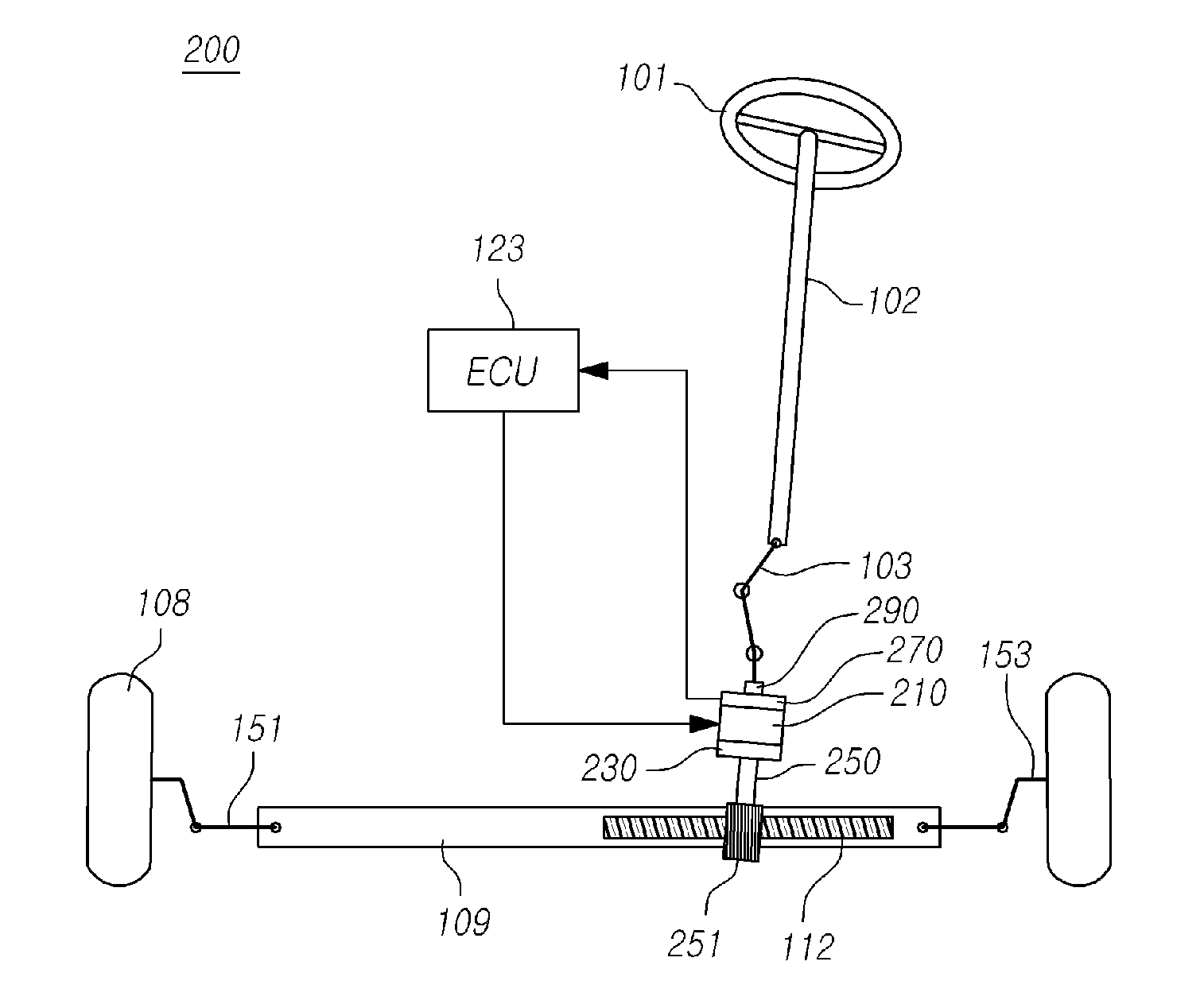
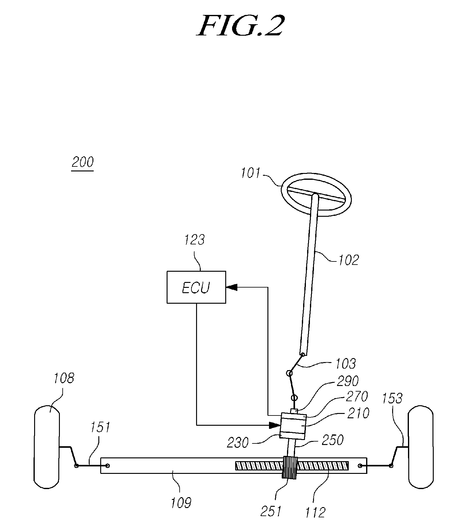
[0027]FIG. 2 is a view illustrating a configuration of an electric power steering apparatus provided with a reducer according to an exemplary embodiment of the present invention. FIG. 3 is a cross-sectional view for a part of FIG. 2. FIG. 4 is a perspective view of an example of a reducer which may be employed in the configuration illustrated in FIG. 2. FIG. 5 is a perspective view illustrating another example of a reducer of FIG. 2 which may be employed in the configuration illustrated in FIG. 2. FIGS. 6 and 7 are exploded perspective views of the reducer of FIG. 5.

[0028]As illustrated in the drawings, a reducer 230 according to an exemplary embodiment of the present invention includes: an eccentric cam 315 formed with a coupling hole 613 in which one end of a hollow motor shaft 311 of a motor 210 is fitted; a step gear 350 including a large-diameter porti...


PUM


Abstract

Disclosed are a reducer and an electric power steering apparatus having the same. According to the present invention, an input shaft, a driving shaft, and a pinion shaft are coaxially arranged. Thus, a conventional configuration, in which a motor inevitably protrudes, can be improved to prevent the motor from interfering with the other structures. Therefore, a layout configuration in an apparatus can be compactly formed.

Description

CROSS-REFERENCE TO RELATED APPLICATION[0001]This application claims priority from and the benefit under 35 U.S.C. §119(a) of Korean Patent Application No. 10-2013-0040763, filed on Apr. 15, 2013, which is hereby incorporated by reference for all purposes as if fully set forth herein.BACKGROUND OF THE INVENTION[0002]1. Field of the Invention[0003]The present invention relates to a reducer and an electric power steering apparatus having the same, and more particularly to a reducer which improves a conventional configuration, in which a motor inevitably protrudes since a motor shaft, an input shaft, a driving shaft, a pinion shaft, etc. are coaxially arranged, to be capable of preventing the motor from interfering with other structures such that a layout configuration in an apparatus can be compactly formed, and an electric power steering apparatus having the reducer.[0004]2. Description of the Prior Art[0005]FIG. 1 is a view illustrating a configuration of a conventional electric powe...

Claims


Application Information

Patent Timeline
IPC IPC(8): B62D5/04F16H1/32
CPCF16H1/321B62D5/0403B62D5/04F16H37/12F16H57/023B62D5/0415F16H1/32F16H2001/324B62D3/12F16H1/28
Inventor KO, KYUNG MINPARK, JUNG SIKCHOI, SEONG HO
Owner HL MANDO CORP
Why Eureka
Try Eureka