Aircraft passenger seating arrangement

a seating arrangement and passenger technology, applied in the field of aircraft passenger seating arrangement, can solve the problems of reducing packing efficiency, affecting privacy and personal space, and affording relatively low privacy levels, so as to achieve efficient packing and minimise the amount of “dead space” between seat units in each row

Active Publication Date: 2014-10-16
ACUMEN DESIGN ASSOCS
View PDF3 Cites 42 Cited by
  • Summary
  • Abstract
  • Description
  • Claims
  • Application Information

AI Technical Summary

Benefits of technology

[0010]wherein the longitudinal axes of the non-aisle-seat units are arranged in-line with one another, and the longitudinal axis of the aisle-seat unit of each pair of seat units is angled relative to the longitudinal axis of the non-aisle-seat unit, so as to provide a passenger access path linking the non-aisle-seat unit of a pair, with the aisle. The present invention recognises that by having the non-aisle-seat units in-line, but the aisle-seat units angled in the claimed manner, a passenger access path linking the non-aisle-seat unit with the aisle can be provided. The passenger access path preferably does not intersect the aisle-seat unit, thereby facilitating a feeling of privacy and personal space for the passengers.
[0017]The passenger access path may adjoin a side of the non-aisle seat. Indeed, embodiments of the invention may facilitate a relatively high packing efficiency because a passenger access space need no longer be provided between the adjacent rows of non-aisle-seats; this may allow the non-aisle-seat units to be closely spaced, and preferably arranged with minimal ‘dead’ space between them.
[0023]As mentioned above, since the arrangement of the present invention facilitates a passenger access path linking the non-aisle-seat unit with the aisle, the need to provide space between adjacent rows of non-aisle seat units (for example in which the passenger of the non-aisle-seat would be able to manoeuvre himself onto the seat unit) is reduced or even removed. The distance (in the longitudinal direction) between adjacent rows of non-aisle seat units is preferably less than the minimum width of a pathway for a passenger to use.
[0024]The distance between adjacent rows of non-aisle seat units may be less than 50 cm, and more preferably less than 30 cm. The distance between adjacent rows of non-aisle seat units may be 9 inches (22.86 cm) or less. The distance between adjacent rows of non-aisle seat units may be 8 inches (20.32 cm) or less. The non-aisle seat units may be arranged substantially without any spacing between them. The pitch of the non-aisle-seat units may be less than, or substantially equal to, the length of the non-aisle-seat units. For example, in some embodiments the non-aisle-seat units may be arranged substantially end-to-end. In other embodiments the non-aisle seat units may overlap one-another (for example the leg-receiving end of one non-aisle seat unit may be located underneath the head-receiving end of the non-aisle seat unit in the row in front). By providing an arrangement in which the non-aisle-seat units are arranged close together (or overlapping), the amount of “dead space” between the seat units in each row can be minimised, resulting in especially efficient packing. Indeed, in embodiments of the present invention, there may only need to be such “dead space” in the front or rear row of seat units in a column.
[0027]At least one of the seat units, and more preferably the passenger supporting surface of the seat unit, at at least one end, and preferably both ends, may be narrower than at the centre. For example, the end(s) of the seat units may be relatively narrow as a result of a step change in width, or may be tapered (for example into a curved, triangular, or trapezoidal shape). By shaping the seat unit, and / or passenger supporting surfaces, in any of the above-mentioned ways, the seat units may be arranged in a relatively space efficient manner. In particular, these embodiments of the invention recognise that the full width of the seat unit is not necessary at its ends (due to the narrowness of a passenger's head and feet), and by narrowing the seat unit in at least one of these ends for an angled aisle seat unit, the unit need not protrude as far into the aisle. Alternatively or additionally, part of the angled aisle seat unit may be received adjacent the narrow region of the non-aisle-seat unit, thereby also reducing the total width of the pair of units.
[0030]In some embodiments of the invention, the aisle seat unit may extend, or be extendable, beyond one end of the non-aisle-seat unit (i.e. in the longitudinal direction), but not necessarily into the space behind it. In other embodiments of the invention, a notional space envelope, having a width corresponding to the maximum width of the non-aisle-seat unit, may extend either end of each non-aisle-seat unit. The aisle-seat unit may be arranged to extend, or be extendable, into said notional space envelope of the respective non-aisle-seat unit. The passenger supporting surface of the aisle-seat unit may be arranged to extend into a notional space envelope having a width corresponding to the maximum width of the passenger supporting surface of the non-aisle-seat unit, and extending either end of that non-aisle-seat unit. These arrangements have been found to provide a particularly efficient use of space because some of the length of the aisle-seat unit (such as the foot or head receiving end) may be accommodated in the space behind the non-aisle-seat unit, thereby reducing the overall width of the pair of seat units.

Problems solved by technology

Privacy and the clear ownership of personal space are becoming an increasingly important issue with passengers.
Whilst many of the above-mentioned arrangements may improve the packing efficiency of the seat units, they may afford relatively low levels of privacy.
This can detrimentally affect the feeling of privacy and personal space for the passengers in one or both of the relevant seat units.
Such arrangements tend to come at the cost of the packing efficiency being reduced.

Method used


Image

  • Aircraft passenger seating arrangement
  • Aircraft passenger seating arrangement
  • Aircraft passenger seating arrangement

Examples


first embodiment

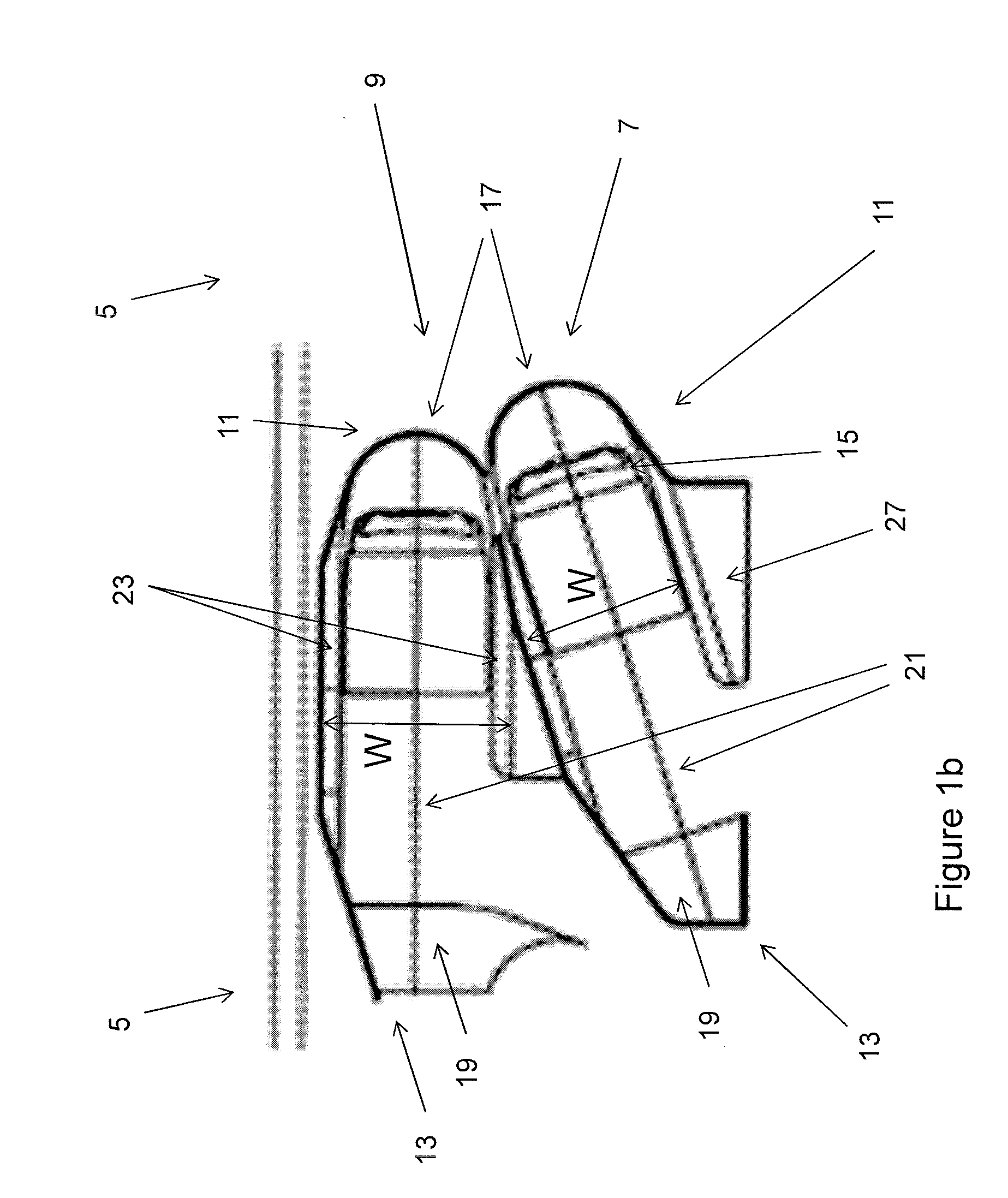
[0084]In the invention the aisle-seat units 7 are angled at 18 degrees to the longitudinal axis 21 of the non-aisle-seat 9. Since the non-aisle-seat units are also parallel to the longitudinal axis 25 of the cabin, the aisle-seat units are also angled at 18 degrees to this cabin axis. Such an orientation has been found to be sufficient to provide above-mentioned advantages of the invention but does not require the aisle-seat unit to meet the crashworthiness criteria of seats angled above 18 degrees.

[0085]In the first embodiment of the invention, the seat units 7, 9 are all forward facing and angled outwardly with respect to the longitudinal axis 21 of the non-aisle-seat units 9; the head-receiving ends 11 of the seat units 7, 9 in each pair 5 are proximal to one another, and the foot-receiving ends 13 of the seat units 7, 9 in each pair 5 are distal from one another. The ottoman 19 and a side table 27 of each aisle-seat unit 7 therefore border the aisle 3. The ottoman 19 and table 2...

second embodiment

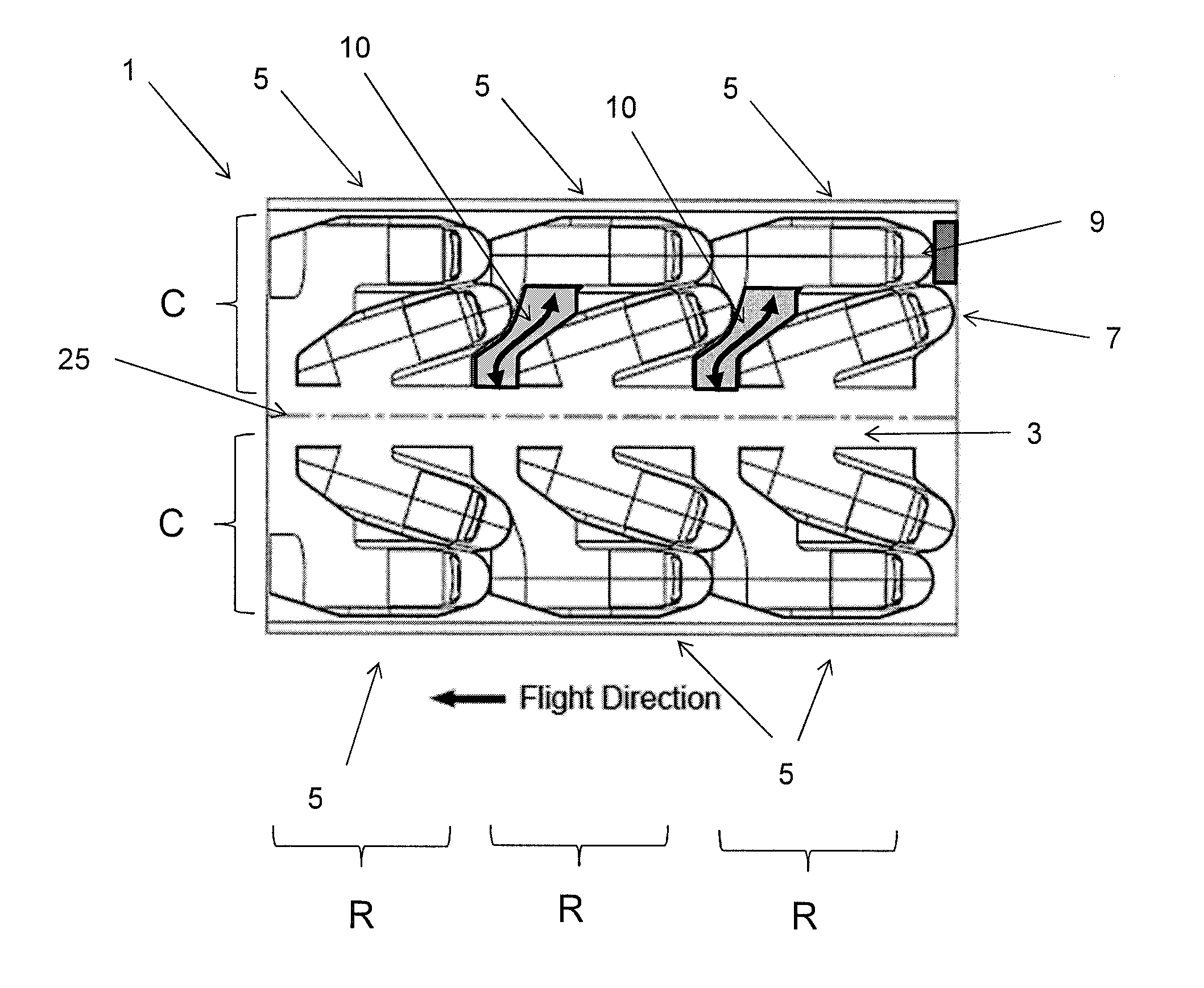
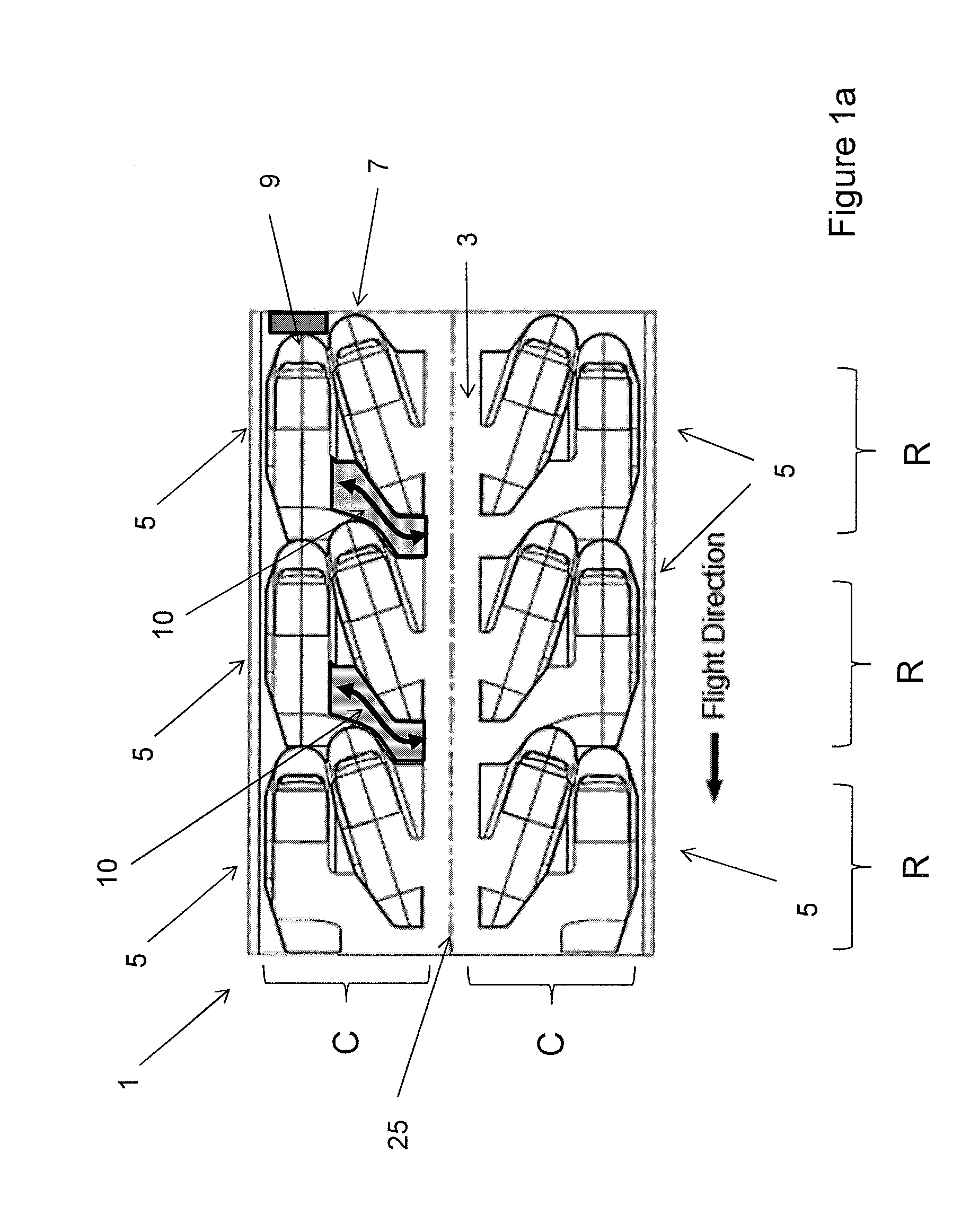
[0087]Firstly, the seating arrangement of the second embodiment is a 2-4-2 arrangement in which a central column C having a width of four seat units 7, 9 (two pairs of seat units 5) extends along the longitudinal axis of the cabin 1, with aisles 3 extending either side thereof. Each row R of the central column C comprises two, inner, seat units 9 forming the non-aisle-seat units 9 of each pair 5 and two outer aisle-seat units 7 having longitudinal axes 21 angled relative to the longitudinal axis 21 of the non-aisle-seat units 9 (see FIG. 2b) such that a passenger access path 10 to the non-aisle-seat unit 9 is provided. In FIG. 1a and subsequent Figures, a passenger access path 10 is, for the sake of clarity, typically only labelled for one of the pairs of seat units. It will be appreciated however, that a passenger access path is, in fact, provided in the corresponding gap between aisle-seat units in the other pairs of seat units shown.

[0088]The seat units 7, 9 are of a different st...

fourth embodiment

[0090]FIG. 4a shows the invention in which the seat units 7, 9 are arranged in a 2-2-2 formation. The pairs of seat units 5 in the central column C are identical in structure to those on the right-hand side of the cabin. Although the seat units in each row R of the central column of seat units are accessible from the surrounding aisles 3 (reducing the need for the passenger access path), it is advantageous to provide pair of seat units 5 in accordance with the invention because of the relatively high seat packing density provided (see above), and to ensure uniform seating within the cabin 1.

[0091]FIG. 4b shows a variant of the fourth embodiment of the invention in which the seat units 7, 9 are arranged in a 2-3-2 formation. The pairs of seat units 5 in the central column C are the same as those in FIG. 4a except that adjacent to the non-aisle-seat unit, a further seat unit is also fitted. The central non-aisle-seat unit in the central column is accessible from the upper aisle 3 via ...


PUM


Abstract

A passenger seating arrangement in an aircraft cabin includes a plurality of pairs of seat units, the pairs of seat units being located directly behind one another, and each seat unit having a longitudinal axis. Each pair of seat units includes an aisle-seat unit and a non-aisle-seat unit. The longitudinal axes of the non-aisle-seat units are arranged in-line with one another, and the longitudinal axis of the aisle-seat unit of each pair of seat units is angled so as to provide a passenger access path linking the non-aisle-seat unit of a pair, with the aisle.

Description

TECHNICAL FIELD[0001]The present invention relates to an aircraft passenger seating arrangement, and to an aircraft passenger seat assembly for use in such a passenger seating arrangement.BACKGROUND OF THE INVENTION[0002]Aircraft seating arrangements in which seat units face in a direction parallel to the longitudinal axis of the aircraft, and are arranged in-line with one another are well known and are still commonly found in economy class seating. Various seating arrangements that seek to more efficiently pack seat units have been suggested. In recent years, there has been a particular focus towards efficiently packing convertible seat units that have both a seat configuration, and a bed configuration. These convertible seat units are typically provided in business class or first class cabins of an aircraft. In the seat configuration, the seat unit typically provides a relatively upright seat, whereas in the bed configuration, the seat unit tends to form a substantially planar sur...

Claims


Application Information

Patent Timeline
Patent Type & Authority Applications(United States)
IPC IPC(8): B64D11/06
CPCB64D2011/062B64D11/06B64D11/0641B64D11/0604B64D11/0601
Inventor DRYBURGH, IAN HAMILTONMCKEEVER, JOHN DAVID HENRYERSAN, ALI
Owner ACUMEN DESIGN ASSOCS
Why Eureka
Try Eureka