Connector

a technology of connecting connectors and connectors, applied in the direction of coupling device details, coupling contact members, coupling device connections, etc., can solve the problems of difficult contact section of matching connectors, adversely affecting any of the electronic components arranged on the substrate, and difficult to match male connectors, etc., to achieve reliable electric connection and reliable electrical connection

Inactive Publication Date: 2003-01-30
L E TECH
View PDF0 Cites 3 Cited by
  • Summary
  • Abstract
  • Description
  • Claims
  • Application Information

AI Technical Summary

Benefits of technology

[0012] With a connector according to the invention, since the contact section is arranged in the engagement space at a position shifted toward the outer periphery so as to be invisible from the front side of the insertion opening, if the user inserts by mistake a screw driver through the insertion opening, the front end of the screw driver would not touch the contact section of the female connector to adversely affect any of the electronic components arranged on the substrate. When the contact section is arranged at a position shifted toward the outer periphery so as to be invisible from the front side of the insertion opening, it may be difficult for the matching connector (male connector) to adojoin the contact section if the matching connector is inserted straight into the engagement space. However, since a connector according to the invention is provided with a guide section for guiding the matching connector inserted into the engagement space through the insertion opening to move toward and adojoin the contact section, the contact section of the matching connector can reliably join its counterpart of the connector according to the invention to establish a reliable electric connection therebetween simply by inserting the matching connector into the engagement space through the insertion opening.
[0021] said male connector being profiled so as to make said neck portion to be located in said insertion opening and said front end portion to be free from obstruction in the movement of being inserted into said engagement space and guided by said guide section toward said female contact section.
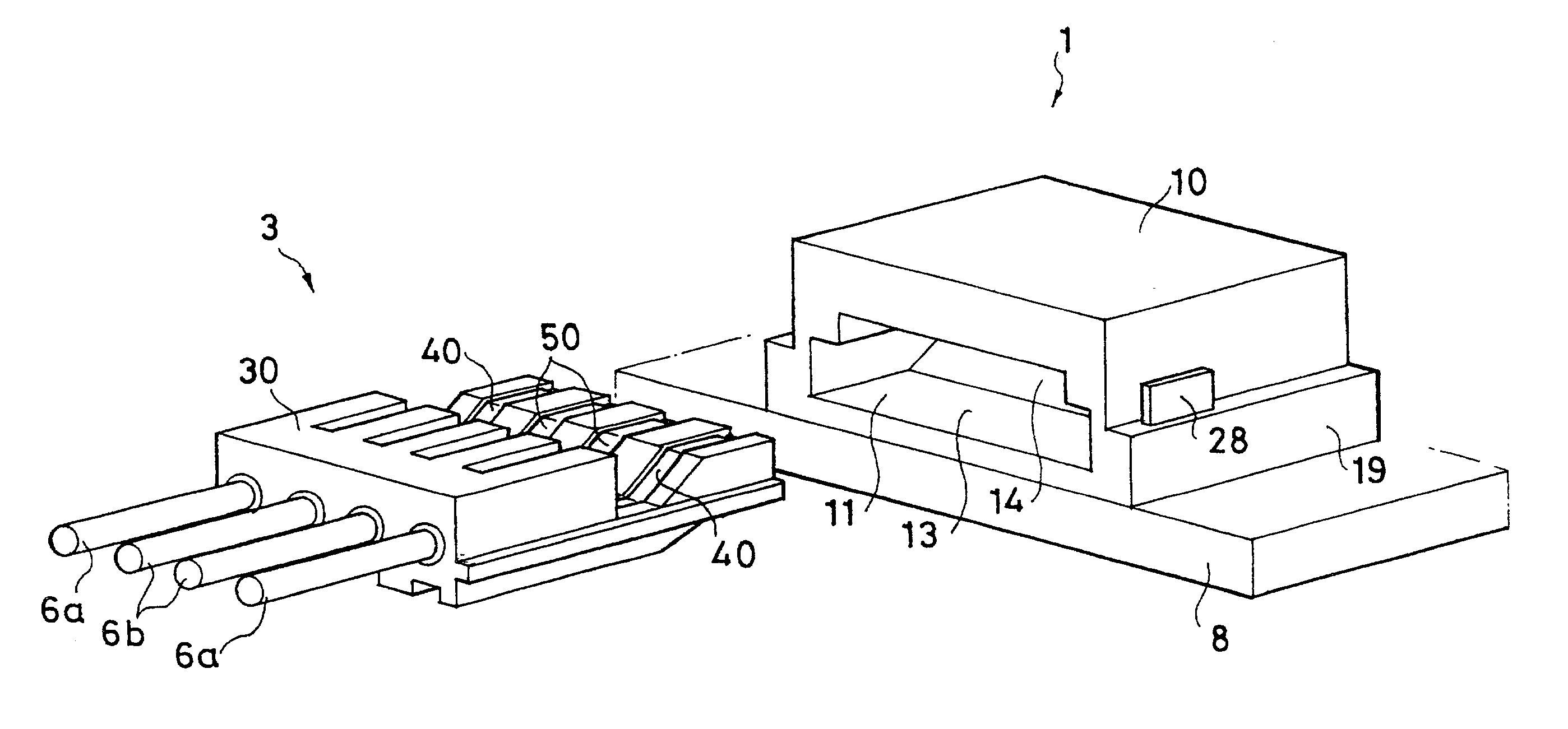
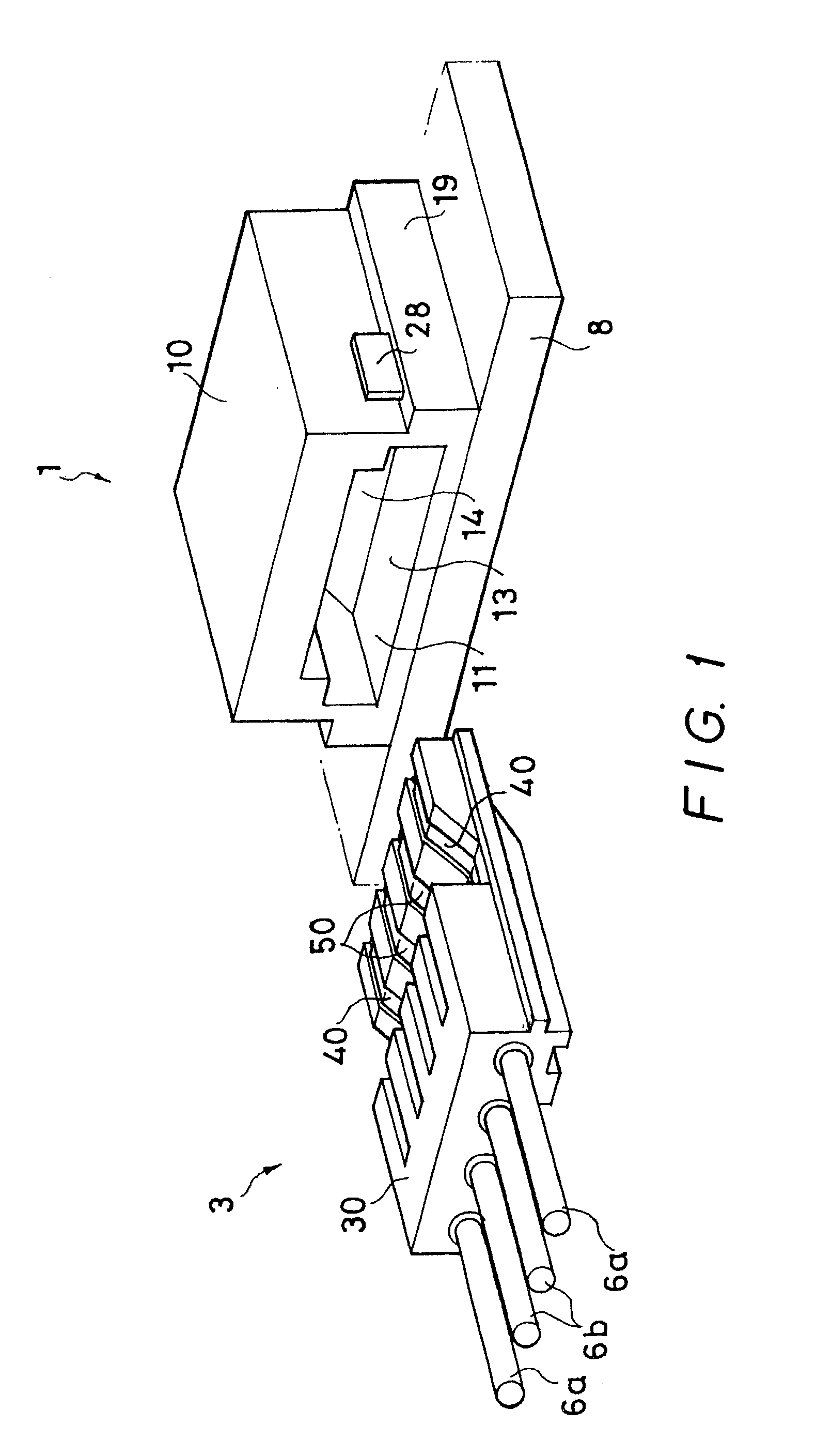
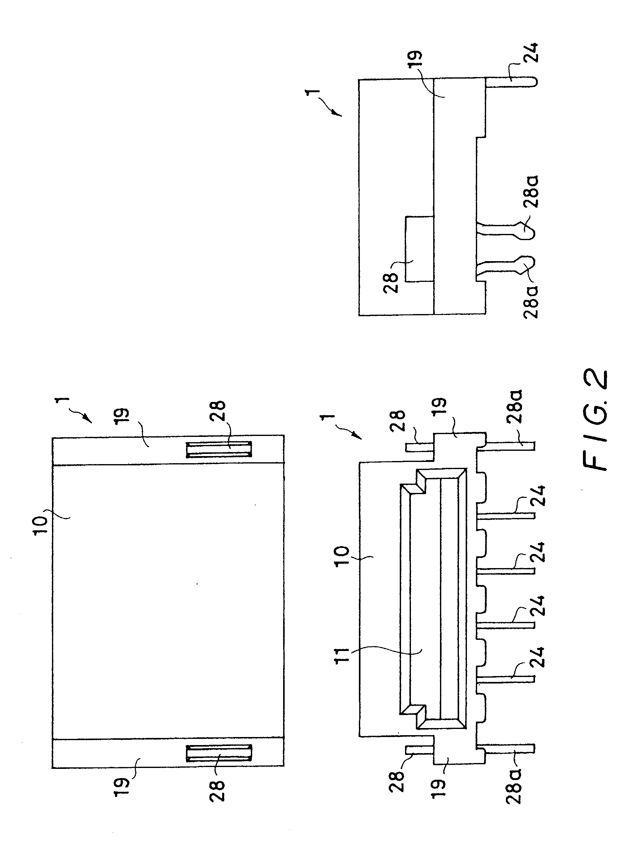
[0022] With a male-female engagement type connector set according to the invention, since the female contact section is arranged in the engagement space at a position shifted toward the outer periphery so as to be invisible from the front side of the insertion opening, if the user inserts by mistake a screw driver through the insertion opening, the front end of the screw driver would not adojoin the female contact section to adversely affect any of the electronic components arranged on the substrate to which the female connector is fitted. When the female contact section is arranged at a position shifted toward the outer periphery so as to be invisible from the front side of the insertion opening, it may be difficult for the contact section of the matching connector (male connector) to adojoin the corresponding respective female contact section if the matching connector is inserted straight into the engagement space. However, since a male-female engagement type connector set according to the invention is provided with a guide section for guiding the front end of the male connector inserted into the engagement space through the insertion opening so as to make it move toward and adojoin the female contact section, the contact section of the male connector can reliably join its counterpart of the female connector to establish a reliable electric connection therebetween simply by inserting the male connector into the engagement space through the insertion opening.
[0024] Preferably, a male-female engagement type connector set according to the invention further comprises a lock means for locking and holding the male housing member relative to the female housing member at a position where the front end of the male connector is completely inserted into the engagement space. At the position where the front end portion of the male connector is completely inserted into the engagement space, the state in which the male contact section adojoin the corresponding female contact section to establish a reliable electric connection therebetween is maintained by the holding section. Therefore, as the male connector is locked to this position by the lock means, the state of the male connector being held by the holding section becomes further reliable. Additionally, if the locking operation of the lock means is accompanied by a feeling of click, the user can easily feel the completion of the insertion of the male connector.
[0025] Preferably, in a male-female engagement type connector set according to the invention, the male connector has a plurality of male contact members provided at the front ends thereof with respective male contact sections that are arranged transversally and exposed and the front end position of the male contact section of at least one of the male contact members is displaced from the front end position of the male contact section of the other male contact members along the direction of insertion so that the male contact members are connected with the respective female contact members with a time lag. With this arrangement, when the male connector is connected to the female connector, the grounding contact member and the power supply contact member of the male connector may be connected first with their respective counterparts of the female connector and the signal contact members of the male connector may be connected subsequently with their respective counterparts of the female connector to give rise to a time lag for electric connection. Then, any possible adverse effect of the electronic components on the related electronic connected by way of the connectors can be minimized.

Problems solved by technology

Then, since the contact section of the female connector of the conventional male-female engagement type connector set appears to be projecting toward the insertion opening in the engagement space of the housing of the female connector, if the user mistakenly inserts a metal rod such as a screw driver into the engagement space through the insertion opening, the front end of the metal rod can touch the contact section of the female connector to give rise to short-circuiting and / or grounding on the part of the contact section and consequently adversely affect any of the electronic components arranged on the substrate and connected to female connector.
When the contact section is arranged at a position shifted toward the outer periphery so as to be invisible from the front side of the insertion opening, it may be difficult for the matching connector (male connector) to adojoin the contact section if the matching connector is inserted straight into the engagement space.
When the female contact section is arranged at a position shifted toward the outer periphery so as to be invisible from the front side of the insertion opening, it may be difficult for the contact section of the matching connector (male connector) to adojoin the corresponding respective female contact section if the matching connector is inserted straight into the engagement space.

Method used


Image

  • Connector
  • Connector
  • Connector

Examples


Embodiment Construction

[0036] The present invention will be described in greater detail by referring to the accompanying drawings that illustrate preferred embodiments of the invention. FIG. 1 is a schematic perspective view of a first embodiment of male-female engagement type connector set according to the invention and comprising a female connector 1 and a male connector 3. The male connector 13 is connected to a plurality (four in this embodiment) of cables 6a, 6a, 6b and 6b, and the female connector 1 is fitted to a printed circuit board 8. Of the four cables connected to the male connector 3, the outer two cables 6a and 6a are power supply cables and the inner two cables 6b and 6b are signal cables. In the following description, the side of each of the connectors that faces the other connector is referred as the front side. Thus, the right side of the female connector 1 is referred as the front side in FIG. 3, whereas the left side of the male connector 3 is referred as the front side in FIG. 5.

[0037...


PUM


Abstract

The object of the present invention to provide a connector, or a male-female engagement type connector set to be more precise, wherein the contact section of the female connector is invisible from the outside through its insertion opening. According to the invention, the above object is achieved by providing a connector comprising: a housing member (10) made of an insulating material and having an engagement space for receiving a matching connector (3) inserted through an insertion opening (11) formed at the front end thereof; a contact member (1) fitted to the housing member (10) and having a contact section (23a) arranged in the engagement space (12); said engagement space (12) being formed internally relative to the insertion opening (11) so as to spread toward the outer periphery of the housing section; said contact section (23a) being arranged in the engagement space (12) at a position shifted toward the outer periphery so as to be invisible from the front side of the insertion opening (11); and said housing member (10) being provided with a guide section (14) for guiding the matching connector (3a) inserted into the engagement space (12) through the insertion opening (11) to move toward and adojoin the contact section (23a).

Description

[0001] This invention relates to an electric connector and, more particularly, it relates to a male-female engagement type connector set wherein the contact of the female connector is made invisible from the outside through its insertion opening.DESCRIPTION OF THE RELATED BACKGROUND ART[0002] Electric connectors are indispensable to almost all electric appliances and being used for connecting power lines and electric signal lines as well as for various other purposes. While many electric connectors are constantly connecting signal lines, some are used only when necessary for connecting testers, sensors, inspection gauges an so on. For instance, the substrate of an IC chip may be proved with a female connector arranged on the substrate thereof and designed for connecting an inspection gauge so that the matching male connector of the inspection gauge may be connected to the female connector to check the performance of the IC chip.[0003] Conventionally, most male-female engagement type...

Claims


Application Information

Patent Timeline
Patent Type & Authority Applications(United States)
IPC IPC(8): H01R13/631H01R12/72H01R12/79H01R13/15H01R13/26H01R13/44H01R13/627H01R13/639H01R24/00
CPCH01R13/26H01R13/44H01R13/627H01R12/79H01R12/727
Inventor SUKAGAWA, SUSUMU
Owner L E TECH
Why Eureka
Try Eureka