
Method for Video Coding Using Blocks Partitioned According to Edge Orientations

a technology of edge orientation and video coding, applied in the field of video coding, can solve problems such as inefficiencies in coding performance, and achieve the effects of reducing the complexity of encoding and decoding systems, reducing the overall bit-rate or file size, and reducing the number of modes

Inactive Publication Date: 2014-10-16
MITSUBISHI ELECTRIC RES LAB INC
View PDF3 Cites 24 Cited by
  • Summary
  • Abstract
  • Description
  • Claims
  • Application Information

AI Technical Summary

Benefits of technology

The patent text describes a method to improve the efficiency of encoding and decoding video images by using statistical dependencies between the optimal partitioning orientation and the prediction direction. This reduces the complexity of the system and the amount of data that needs to be transmitted or stored.

Problems solved by technology

When a transform is applied over an entire prediction residual block, which is the difference between the input block and its prediction, the sharp transitions lead to inefficiencies in coding performance,

Method used


Image

  • Method for Video Coding Using Blocks Partitioned According to Edge Orientations
  • Method for Video Coding Using Blocks Partitioned According to Edge Orientations
  • Method for Video Coding Using Blocks Partitioned According to Edge Orientations

Examples


Embodiment Construction

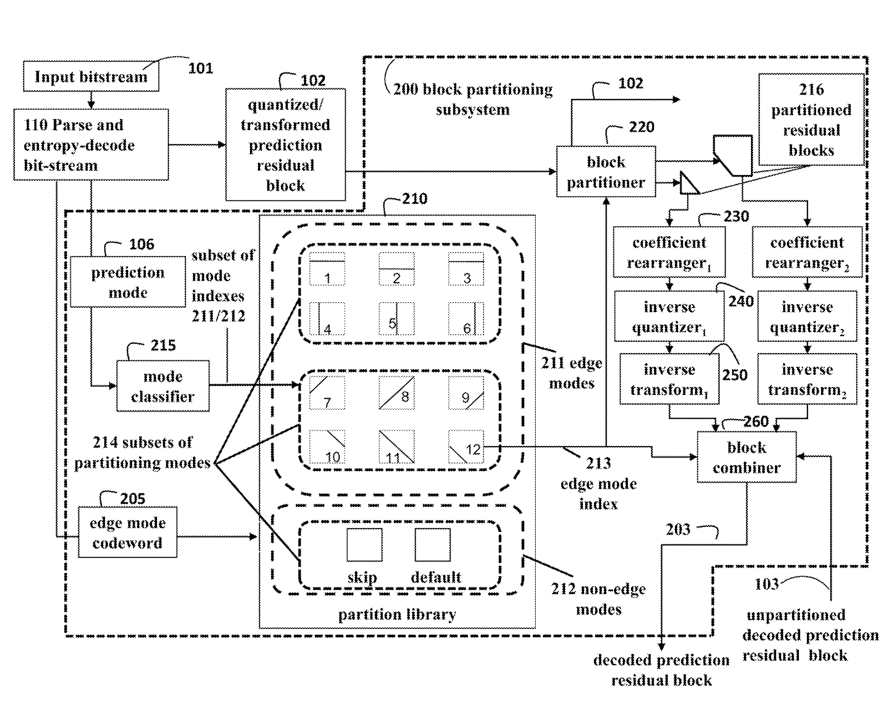
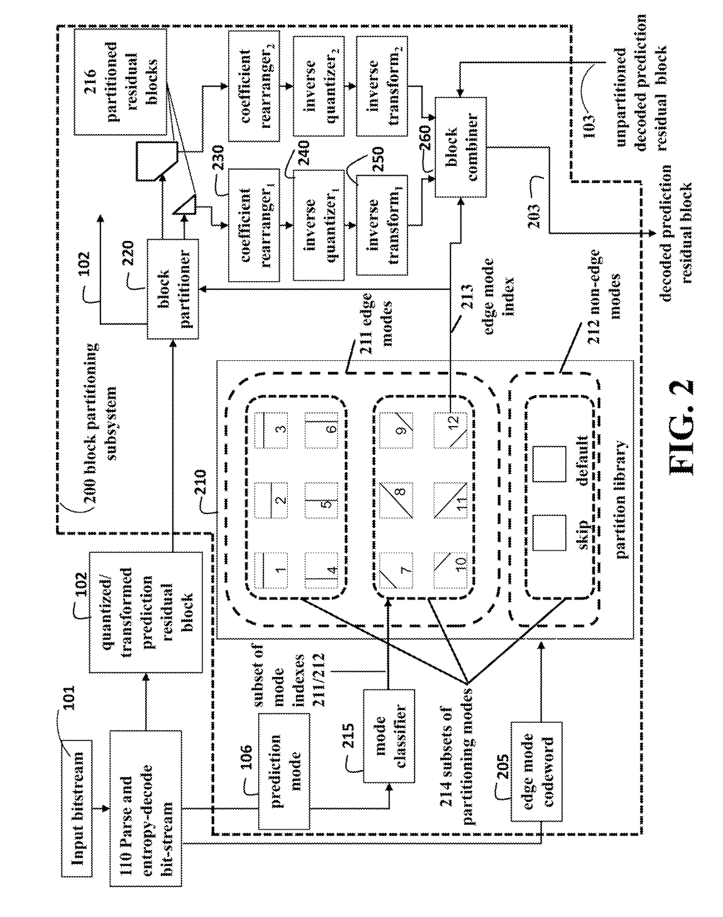
[0024]FIG. 2 schematically shows a block partitioning subsystem 200 of a video decoder according to the embodiments of the invention. The input bitstream 101 is parsed and entropy decoded 110 to produce a quantized and transformed prediction residual block 102, a prediction mode 106 and an edge mode codeword 205, in addition to other data needed to perform decoding.

[0025]The block partitioning subsystem has access to a partition library 210, which specifies a set of modes. These can be edge modes 211, which partition a block in various ways, or non-edge modes 212 which do not partition a block. The non-edge modes can skip the block or use some default partitioning. The figure shows twelve example edge mode orientations. The example partitioning is for the edge mode block having an edge mode index 213.

[0026]Edge modes or non-edge modes can also be defined based on statistics measured from the pixels in the block. For example, the gradient of data in a block can be measured, and if th...


PUM


Abstract

A bitstream corresponding to an encoded video is decoded. The encoded video includes a sequence of frames, and each frame is partitioned into encoded blocks. For each encoded block, an edge mode index is decoded based on an edge mode codeword and a prediction mode. The edge mode index indicates a subset of predetermined partitions selected from a partition library according to the prediction mode. The encoded block is partitioned based on the edge mode index to produce two or more block partitions. To each block partition, a coefficient rearrangement, an inverse transform and an inverse quantization is applied to produce a processed block partition. The processed block partitions are then combined into a decoded block for a video.

Description

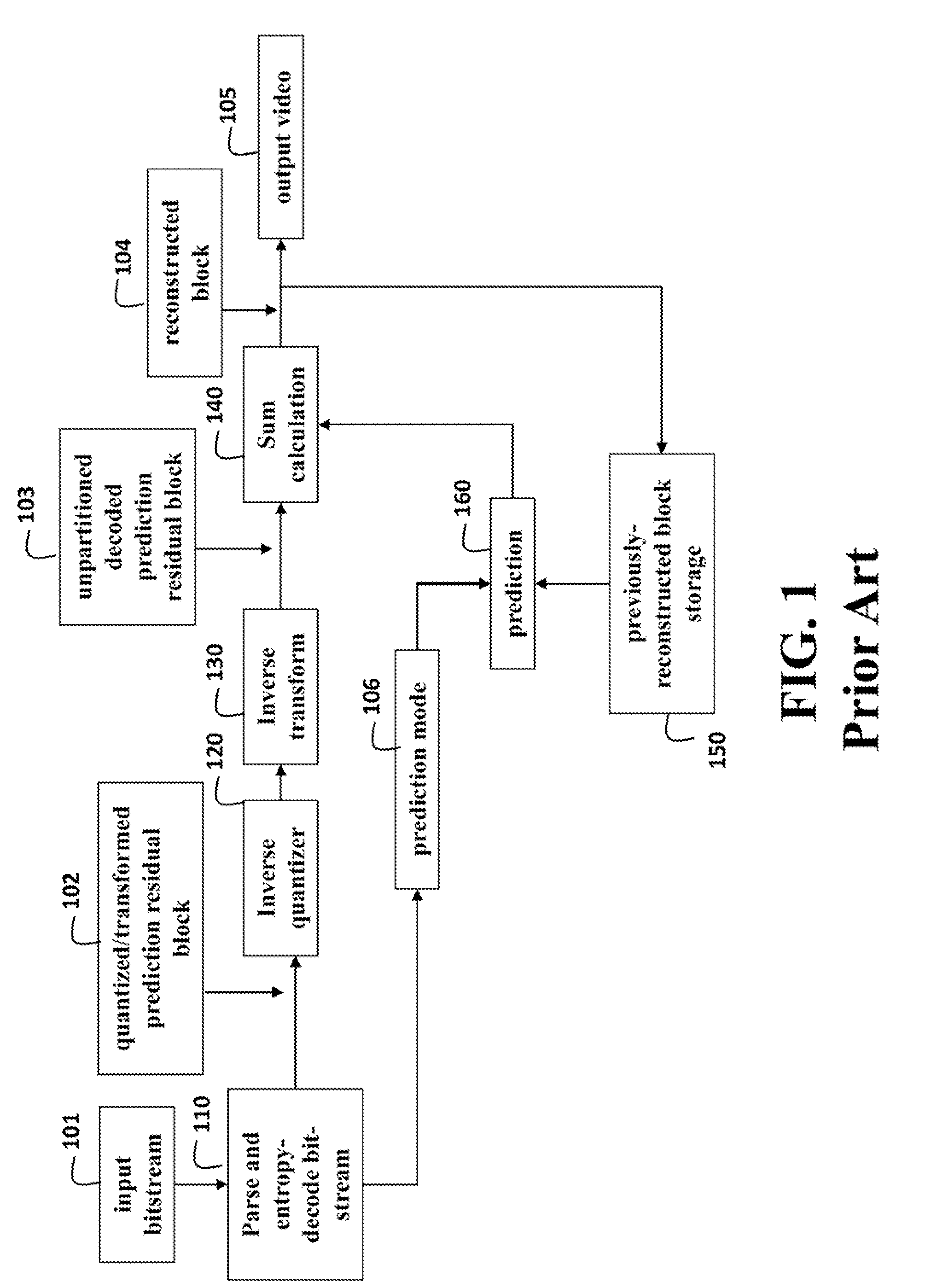
FIELD OF THE INVENTION [0001]This invention relates generally to video coding, and more particularly to partitioning and transforming blocks.BACKGROUND OF THE INVENTION[0002]When videos, images, or other similar data are encoded or decoded, previously-decoded or reconstructed blocks of data are used to predict a current block being, encoded or decoded. The difference between the prediction block and the current block or reconstructed block in the decoder is a prediction residual block.[0003]In an encoder, a prediction residual block is a difference between the prediction block and the corresponding block from an input picture or video frame. The prediction residual is determined as a pixel-by-pixel difference between the prediction block and the input block. Typically, the prediction residual block is subsequently transformed, quantized, and then entropy coded for output to a file or bitstream for subsequent use by a decoder.[0004]FIG. 1 shows a conventional the decoder input is a b...

Claims


Application Information

Patent Timeline
IPC IPC(8): H04N19/124H04N19/61
CPCH04N19/00781H04N19/0009H04N19/159H04N19/176H04N19/119H04N19/147H04N19/46H04N19/61H04N19/12H04N19/124H04N19/14
Inventor COHEN, ROBERT A.HU, SUDENGVETRO, ANTHONY
Owner MITSUBISHI ELECTRIC RES LAB INC
Learn More