Compensation for Optical Multi-Path Interference

a multi-path interference and compensating technology, applied in the direction of distortion/dispersion elimination, fibre transmission, electrical equipment, etc., can solve the problems of multi-path interference (mpi), interference with subsequent transmission, and substantial number of extra signal paths

Active Publication Date: 2014-10-16
AVAGO TECH INT SALES PTE LTD
View PDF5 Cites 46 Cited by
  • Summary
  • Abstract
  • Description
  • Claims
  • Application Information

AI Technical Summary

Problems solved by technology

Multi-path interference (MPI) is an issue that presents itself on single mode fiber optical systems.
For such optical systems, optical connections, including coupling into and out of an optical fiber, can cause reflections which can result in ...

Method used


Image

  • Compensation for Optical Multi-Path Interference
  • Compensation for Optical Multi-Path Interference
  • Compensation for Optical Multi-Path Interference

Examples


Embodiment Construction

[0014]For purposes of this discussion, the term “module” shall be understood to include at least one of software, firmware, and hardware (such as one or more circuits, microchips, processors, or devices, or any combination thereof), and any combination thereof. In addition, it will be understood that each module can include one, or more than one, component within an actual device, and each component that forms a part of the described module can function either cooperatively or independently of any other component forming a part of the module. Conversely, multiple modules described herein can represent a single component within an actual device. Further, components within a module can be in a single device or distributed among multiple devices in a wired or wireless manner.

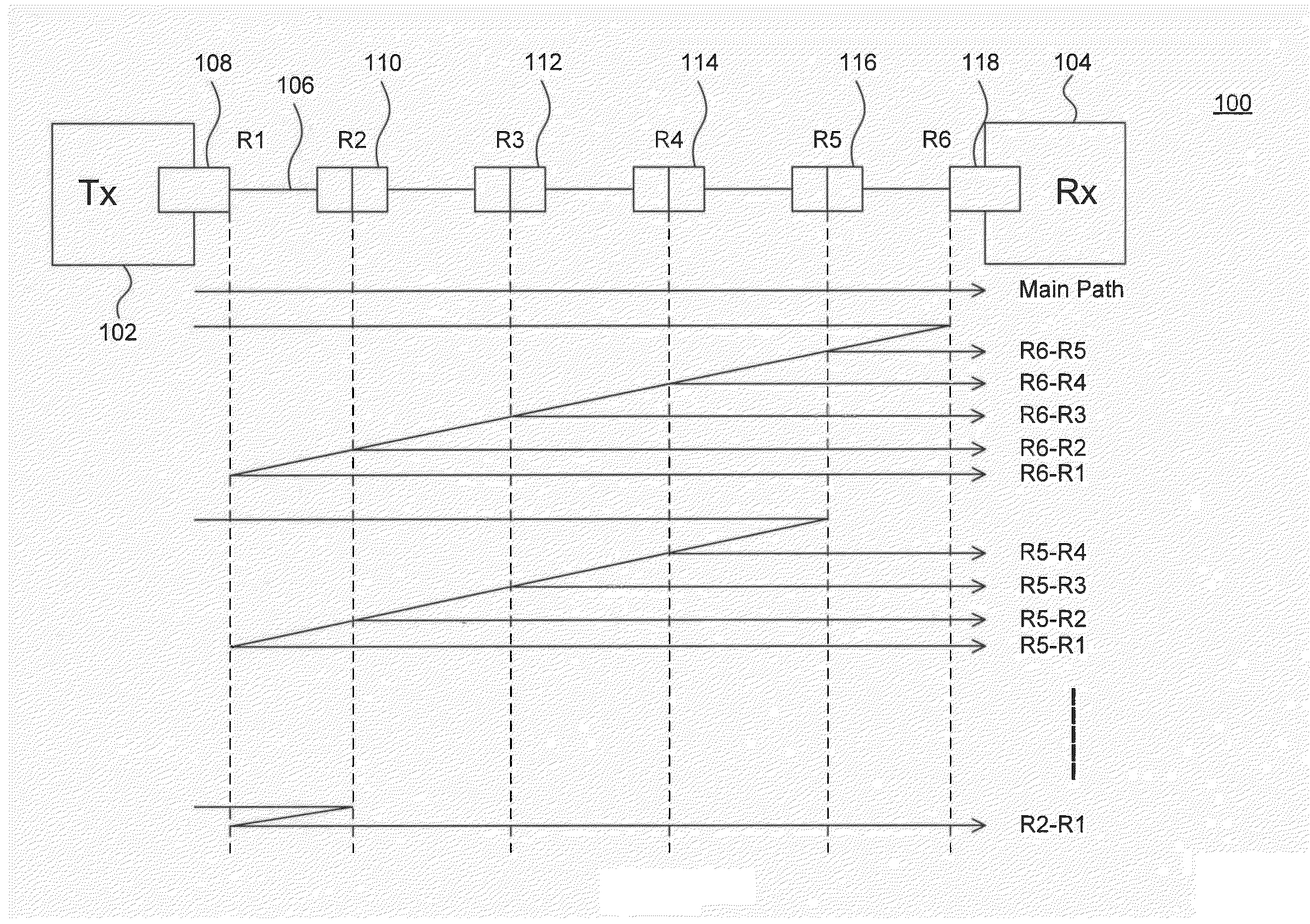
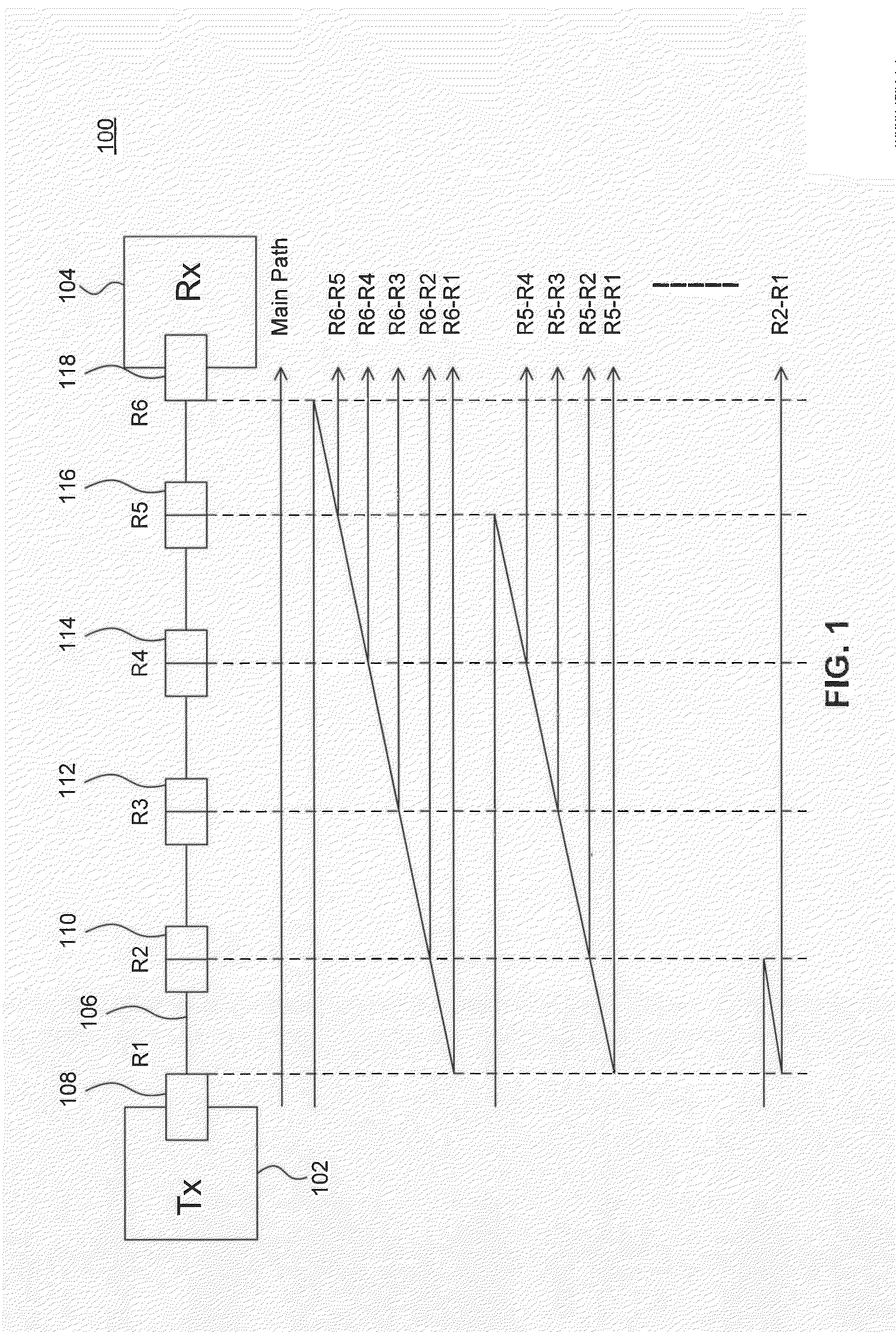
[0015]FIG. 1 illustrates an example optical link 100. Example optical link 100 is provided for the purpose of illustration only and is not limiting of embodiments. As shown in FIG. 1, example optical link 100 inclu...


PUM


Abstract

Systems and methods for optical multi-path interference (MPI) compensation are provided. In an embodiment, a mean MPI signal representing a mean amplitude of the MPI in an input signal is generated and subtracted from a first estimate of transmitted amplitude of the input signal to generate a mean MPI compensated estimate of transmitted amplitude. The mean MPI compensated estimate of transmitted amplitude is sliced to generate a decision of transmitted amplitude of the input signal. The mean MPI signal can be generated using a mean MPI feedback loop or using an iterative feed-forward process. In another embodiment, mean MPI levels corresponding to respective transmitted intensity levels are generated and used to control slice levels of a slicer in order to compensate for MPI.

Description

CROSS-REFERENCE TO RELATED APPLICATIONS[0001]The present invention claims the benefit of U.S. Provisional Application No. 61 / 812,160, filed Apr. 15, 2013, which is incorporated herein by reference in its entirety.FIELD OF THE INVENTION[0002]The present disclosure relates generally to compensation for optical multi-path interference.BACKGROUNDBackground Art[0003]Multi-path interference (MPI) is an issue that presents itself on single mode fiber optical systems. For such optical systems, optical connections, including coupling into and out of an optical fiber, can cause reflections which can result in a substantial number of extra signal paths from the optical transmitter to the optical receiver. The extra signal paths arrive at the receiver with some delay from the main (non-reflected) path signal and can interfere with subsequent transmissions.BRIEF DESCRIPTION OF THE DRAWINGS / FIGURES[0004]The accompanying drawings, which are incorporated herein and form a part of the specification,...

Claims


Application Information

Patent Timeline
IPC IPC(8): H04B10/2507
CPCH04B10/2507H04B10/69H04B10/695H04B10/697H04B10/6971
Inventor BLISS, WILLIAMWANG, JOHN
Owner AVAGO TECH INT SALES PTE LTD
Why Eureka
Try Eureka