Medical device, and the methods of using same

a technology of medical devices and airways, applied in the field of medical devices, can solve the problems of inability to know if the proper placement of the laryngeal mask airway has occurred, medical professionals may not know, and the airway may be difficult to intuba

Active Publication Date: 2014-10-16
WM & DG
View PDF4 Cites 27 Cited by
  • Summary
  • Abstract
  • Description
  • Claims
  • Application Information

AI Technical Summary

Problems solved by technology

This is not a desirable result as the blocking by the epiglottis can cause problems with the airflow through the laryngeal mask airway.
In addition, inappropriate sizing and differences in the anatomy of patients may also impair the proper positioning of the laryngeal mask airway.
Since the insertion is performed blindly, the medical professional will not know if proper placement of the laryngeal mask airway has occurred.
If the epiglottis is at least partially blocking the opening in the tube, this intubation may be difficult.
In addition, the glottis opening quite often does not align with the tube opening which can make this blind insertion difficult and may result in trauma to the laryngeal inlet.

Method used


Image

  • Medical device, and the methods of using same
  • Medical device, and the methods of using same
  • Medical device, and the methods of using same

Examples


first embodiment

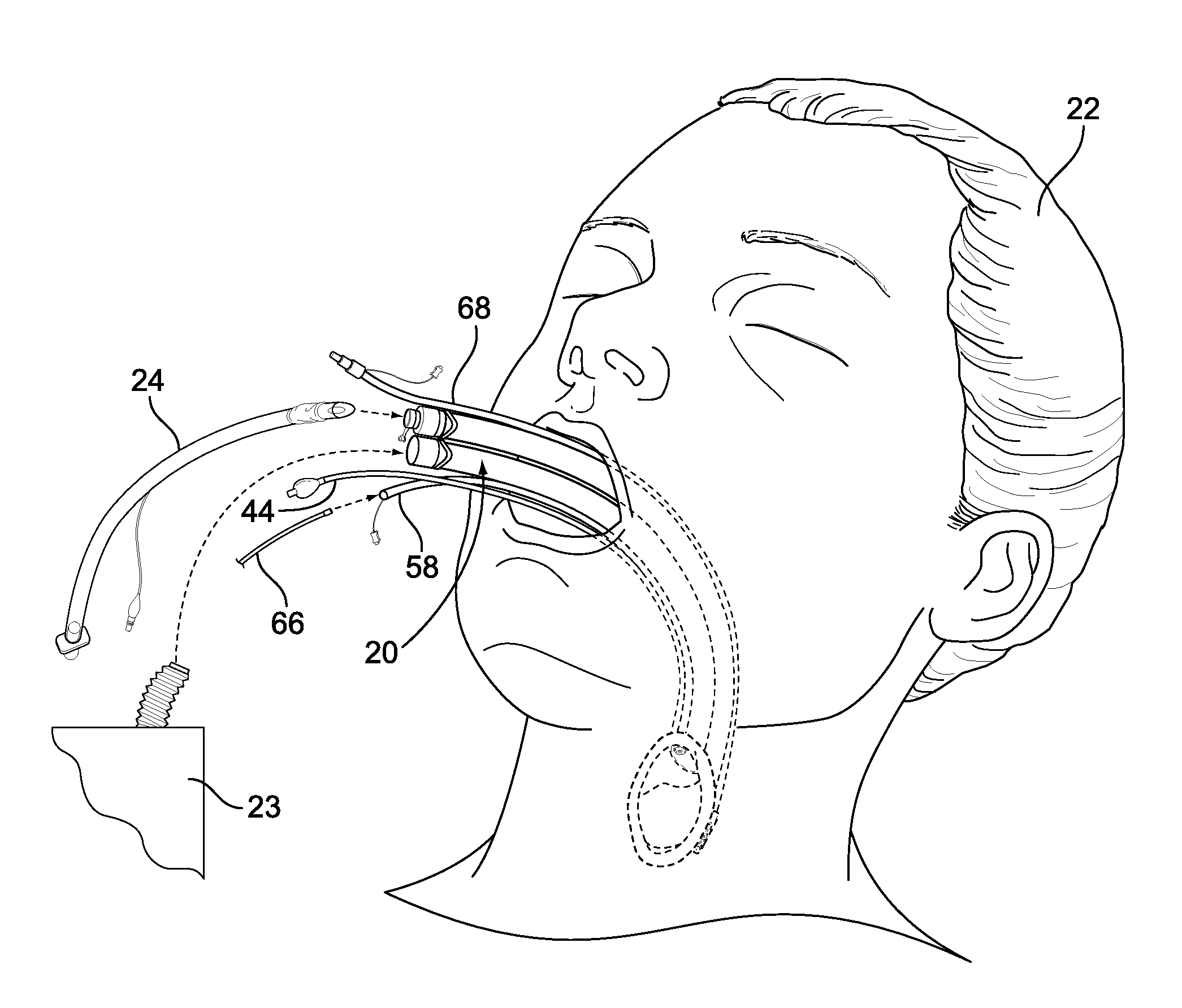
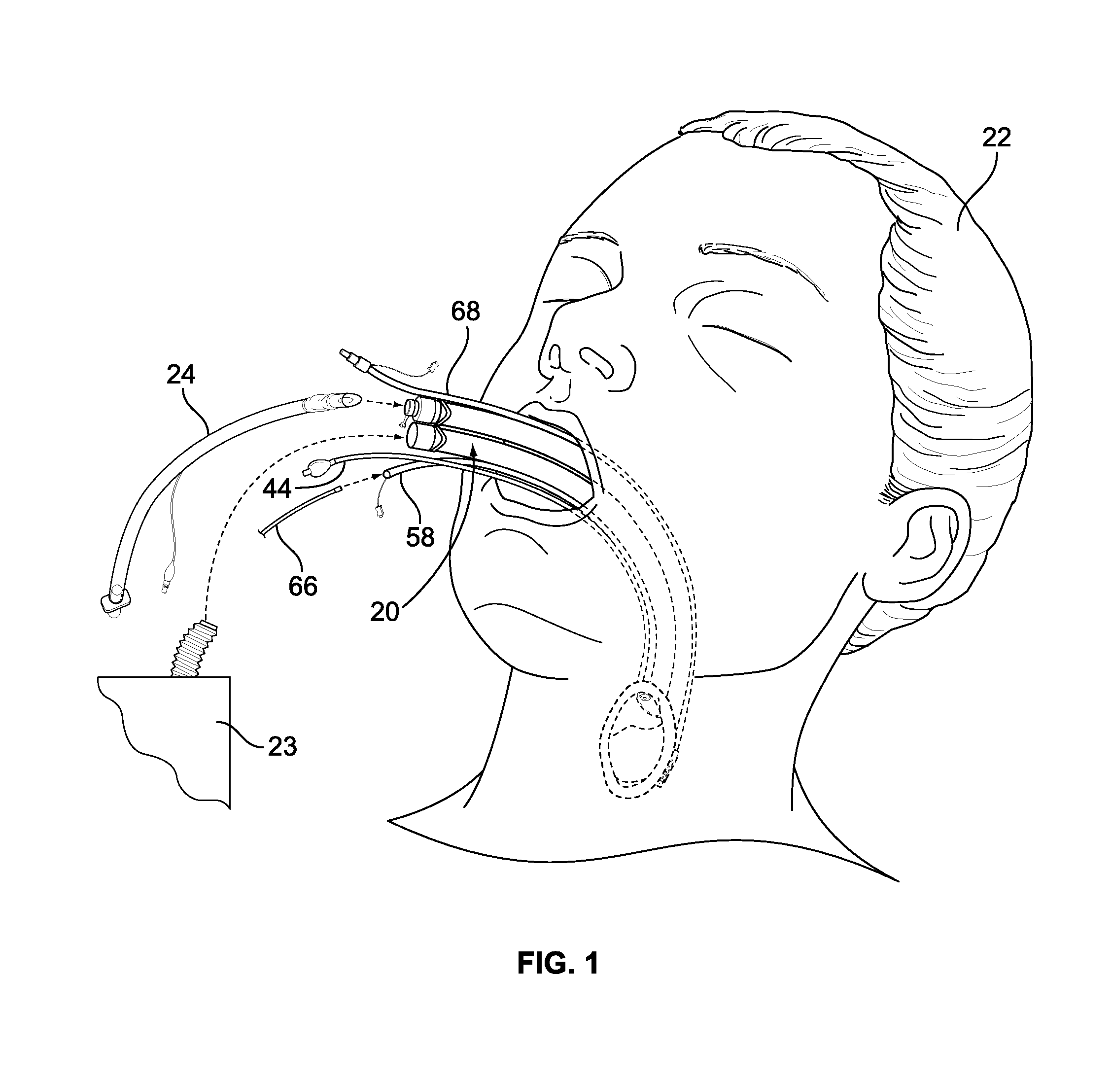
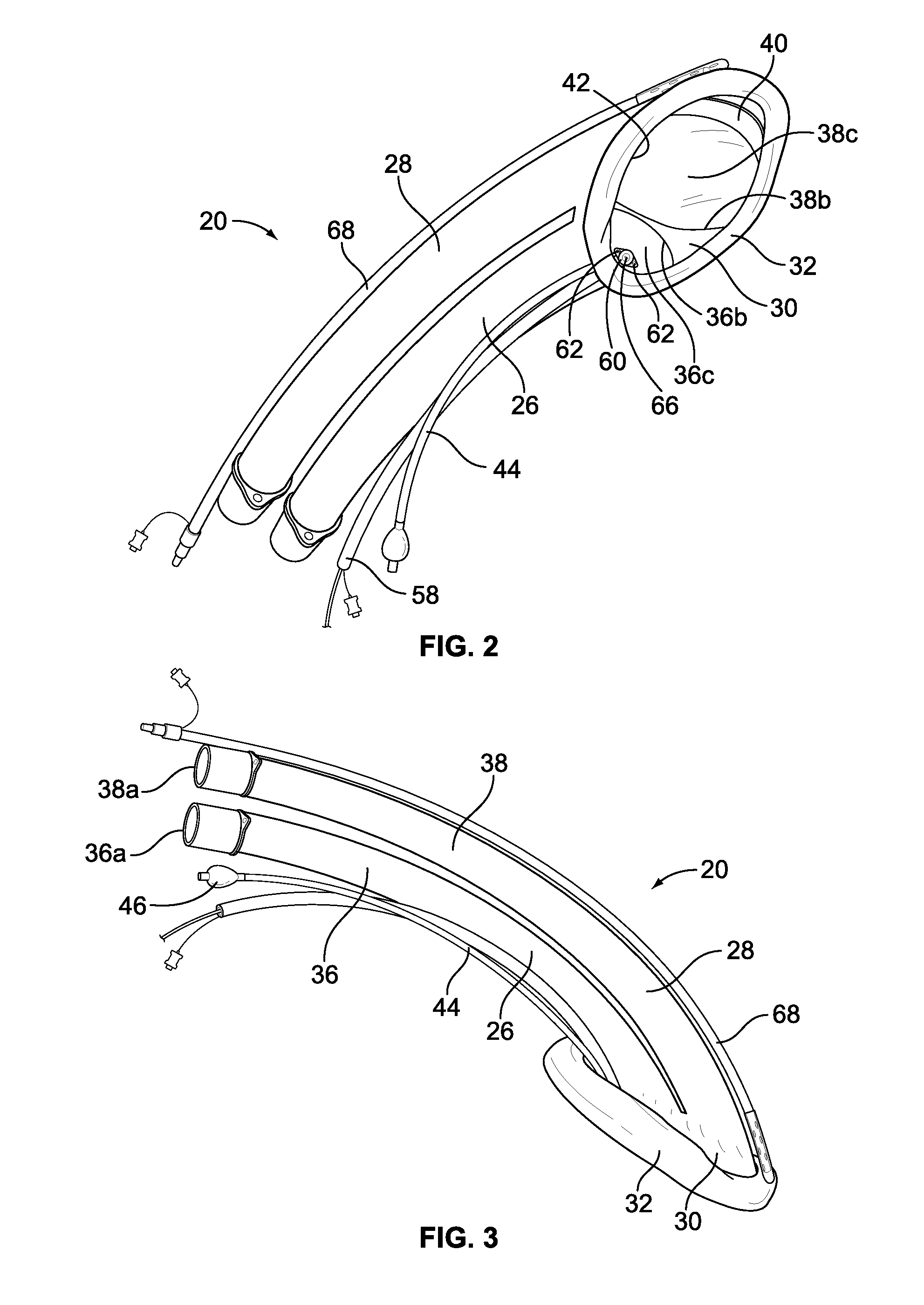
[0055]Attention is invited to the medical device 20 shown in FIGS. 1-8 which shows the specifics of the dual-tube design. [0006] Each tube 26, 28 is formed from a cylindrical wall 36, 38 having a proximal open inlet 36a, 38a (at the end closest to the medical professional), an opposite distal open outlet 36b, 38b (at the end furthest away from the medical professional during use of the medical device 20) and a central passageway 36c, 38c extending through the respective tube 36, 38. Each tube 36, 38 has a centerline 36d, 38d which extends from the proximal inlet 36a, 38a to the distal outlet 36b, 38b. The tubes 26, 28 are curved along the length of each tube 26, 28 and the centerlines 36d, 38d are accordingly curved. Each tube 26, 28 has a diameter which is preferably 15 mm, however, each tube 26, 28 may be bigger or smaller, and / or not of equal diameter with respect to each other. Each tube 26, 28 is formed of a relatively stiff but compliant plastics material and is preferably for...

second embodiment

[0066]Attention is now invited to the medical device 120 shown in FIGS. 9 and 10 which shows the specifics of the dual-tube design.

[0067]Each tube 126, 128 is formed from a cylindrical wall 136, 138 having a proximal open inlet 136a, 138a (at the ends closest to the medical professional), an opposite open distal outlet 136b, 138b (at the ends furthest away from the medical professional during use of the medical device 120) and a central passageway 136c, 138c extending through the respective tube 126, 128. Tube 128 is shown in full line in FIG. 9 to illustrate the construction of the tube 128 (of course, in practice, tube 126 may be opaque such that tube 128 would not be visible along its length). The outlets 136b, 138b generally align with each other. Each tube 126, 128 has a centerline 136d, 138d which extends from the proximal inlet 136a, 138a to the distal outlet 136b, 138b. The tubes 126, 128 are curved along the lengths thereof and the centerlines 136d, 138d are accordingly cur...


PUM


Abstract

A medical device is provided for insertion into a cavity of a patient to visual the internal membranes of the patient. The medical device can be an endotracheal tube, a suction tube, a bronchoscope, a tube changer, an esophageal tube, an intubating tube, an esophageal tube in combination with a separate intubating tube, a device for manipulating the position of the epiglottis of the patient, a stylet, or a tube insertable into the vagina of the patient. The medical device has a camera lumen having a sealed window at one end thereof attached thereto, and a separate camera which is insertable into the camera lumen and is removable from the camera lumen. The camera is used to monitor the internal membranes of the patient during the medical procedure.

Description

[0001]This application is a continuation-in-part application of U.S. Ser. No. 13 / 486,549, filed on Jun. 1, 2012, the disclosure of which is incorporated in its entirety. This application claims the domestic benefit of U.S. Ser. No. 61 / 674,924, filed on Jul. 24, 2012, the disclosure of which is incorporated in its entirety.FIELD OF THE INVENTION[0002]The present invention relates to a medical device for allowing a medical professional to see the internal membranes of a patient during a medical procedure.BACKGROUND OF THE INVENTION[0003]An example of a medical device which medical professionals use to see the internal membranes of a patient is a laryngeal mask airway. A laryngeal mask airway is used to ventilate and to supply anesthetic to a patient during surgery. A laryngeal mask airway is different than an endotracheal tube in that the laryngeal mask airway is positioned in the throat of the patient proximally of the vocal folds, while an endotracheal tube is passed through the voc...

Claims


Application Information

Patent Timeline
Patent Type & Authority Applications(United States)
IPC IPC(8): A61B1/04A61M16/04A61B7/00A61M16/00
CPCA61B1/04A61M16/042A61M16/0057A61M16/04A61B1/05A61B1/0676A61B1/0684A61B1/267A61M16/0463A61M16/0488A61M2205/3375A61M2205/502A61M2230/04A61M16/0409A61B7/003A61B1/00128A61B1/00154A61B1/015A61B1/2676A61B1/303A61B5/435A61M16/0434A61M25/0169A61M2025/0681
Inventor MOLNAR, ROBERT
Owner WM & DG
Why Eureka
Try Eureka