Photoacoustic wave measurement instrument

a technology of photoacoustic waves and measurement instruments, applied in the field of position measurement of targets, can solve problems such as errors generated in the measurement of the position of targets

Inactive Publication Date: 2014-10-16
ADVANTEST CORP
View PDF4 Cites 5 Cited by
  • Summary
  • Abstract
  • Description
  • Claims
  • Application Information

AI Technical Summary

Benefits of technology

[0011]It is therefore an object of the present invention to provide a photoacoustic wave measurement instrument capable of precisely measuring the position of a photoacoustic wave generation part.

Problems solved by technology

In this case, an error is generated in the measurement of the position of the target.

Method used


Image

  • Photoacoustic wave measurement instrument
  • Photoacoustic wave measurement instrument
  • Photoacoustic wave measurement instrument

Examples


first embodiment

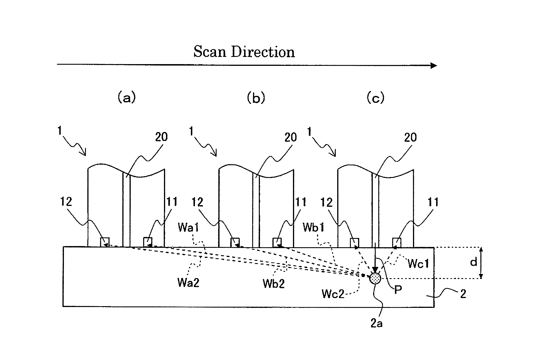
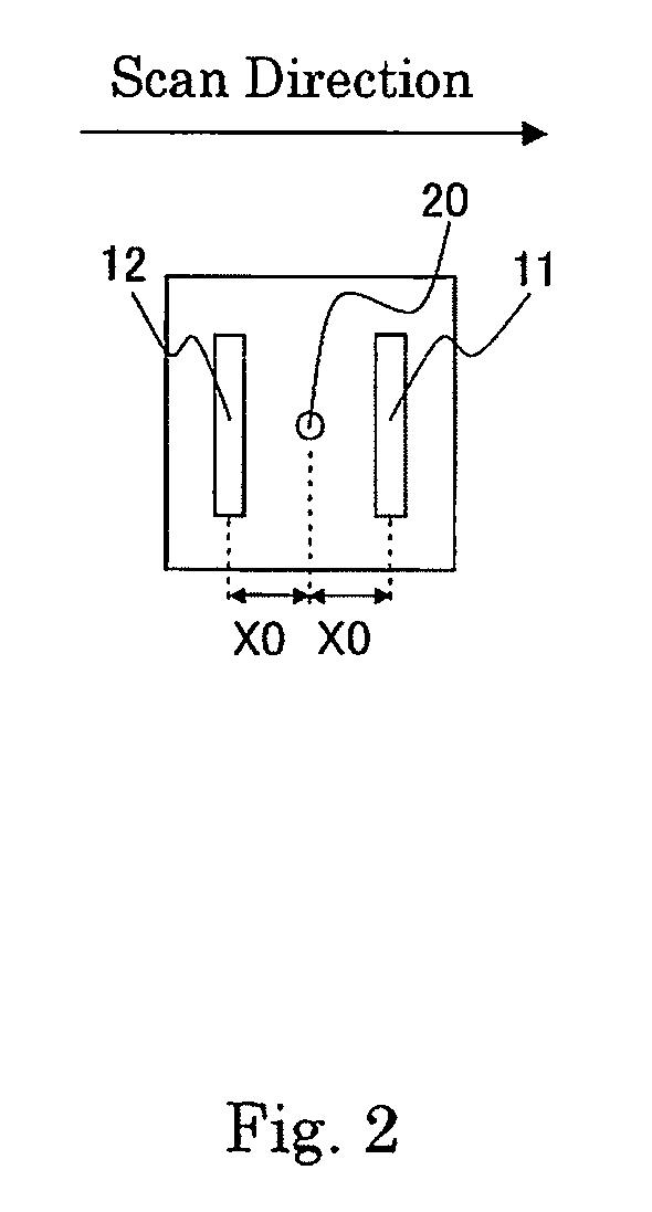
[0033]FIG. 1 is a cross sectional view of a photoacoustic wave measurement instrument 1 according to a first embodiment of the present invention. FIG. 2 is a plan view of the photoacoustic wave measurement instrument 1 according to the first embodiment of the present invention. The photoacoustic wave measurement instrument 1 includes photoacoustic wave detection units 11 and 12, and an optical fiber (light output unit) 20. The photoacoustic wave measurement instrument 1 is in contact with a measurement object 2, and is scanned on the measurement object 2 from left to right, for example.

[0034]FIG. 1(a) shows the photoacoustic wave measurement instrument 1 positioned far from blood 2a. When the photoacoustic wave measurement instrument 1 shown in FIG. 1(a) is scanned to right, the photoacoustic wave measurement instrument 1 is positioned slightly far from the blood 2a as shown in FIG. 1(b). When the photoacoustic wave measurement instrument 1 shown in FIG. 1(b) is scanned to right, th...

second embodiment

[0084]The photoacoustic wave measurement instrument 1 according to a second embodiment is different from the photoacoustic wave measurement instrument 1 according to the first embodiment in that the photoacoustic wave measurement instrument 1 according to the second embodiment includes at least three photoacoustic wave detection units.

[0085]FIG. 5 includes a plan view (FIG. 5(a)) of the photoacoustic wave measurement instrument 1 according to the first embodiment of the present invention and a plan view (FIG. 5(b)) of the photoacoustic wave measurement instrument 1 according to the second embodiment of the present invention.

[0086]The photoacoustic wave measurement instrument 1 according to the second embodiment of the present invention includes photoacoustic wave detection units 11, 12, 13, and 14, and the optical fiber (light output unit) 20. In the following section, like components are denoted by like numerals as of the first embodiment, and will be described in no more details.

[...

third embodiment

[0121]A third embodiment is different from the first embodiment in such a point that the distance between the photoacoustic wave detection unit 11 and the optical fiber 20 and the distance between the photoacoustic wave detection unit 12 and the optical fiber 20 are different from each other (refer to FIG. 8(b)).

[0122]FIG. 8 includes a cross sectional view (FIG. 8(a)) and a plan view (FIG. 8(b)) of the photoacoustic wave measurement instrument 1 according to the third embodiment of the present invention. The photoacoustic wave measurement instrument 1 includes the photoacoustic wave detection units 11 and 12, and the optical fiber (light output unit) 20. Hereinafter, like components are denoted by like numerals as of the first embodiment of the photoacoustic wave measurement instrument 1, and will be described in no more details.

[0123]The optical fiber (light output unit) 20 is the same as that of the first embodiment, and a description thereof, therefore, is omitted. The photoacous...


PUM


Abstract

A photoacoustic wave measurement instrument include a light output unit and at least three photoacoustic wave detection units. The light output unit outputs light. The at least three photoacoustic wave detection units respectively receive photoacoustic waves generated by the light in a measurement object, and convert the photoacoustic wave into electric signals. At least two of the photoacoustic wave detection units have extension directions parallel with or intersecting with each other. At least one of the photoacoustic wave detection units other than the at least two photoacoustic wave detection units has an extension direction intersecting with the extension directions of the at least two photoacoustic wave detection units.

Description

BACKGROUND ART[0001]1. Field of the Invention[0002]The present invention relates to a position measurement of a target by means of a photoacoustic sensor.[0003]2. Related Art[0004]It is conventionally known to measure a measurement object by detecting photoacoustic waves by using at least two photoacoustic sensors (refer to Patent Document 1). The photoacoustic sensor radiates light upon the measurement object. Then, the light is absorbed by a target in the measurement object. As a result, the target (photoacoustic wave generation part) generates photoacoustic waves. The photoacoustic sensor detects the photoacoustic wave. If the photoacoustic sensor is positioned directly above the target, the photoacoustic sensor can detect the photoacoustic wave. As a result, the position of the target can be measured.PRIOR ART DOCUMENTS[0005](Patent Document 1) Japanese Patent Application Laid-Open (Kokai) No. 2004-201749[0006](Patent Document 2) Japanese Translation of PCT International Applica...

Claims


Application Information

Patent Timeline
Patent Type & Authority Applications(United States)
IPC IPC(8): A61B5/00
CPCA61B5/0095A61B5/68A61B5/489A61B2562/04A61B2562/046
Inventor IDA, TAIICHIRO
Owner ADVANTEST CORP
Why Eureka
Try Eureka