Cooling Fan Having a Axial-Air-Gap Motor and a Method for Determining the Dimensional Proportion of the Motor

a technology of axial air gap and cooling fan, which is applied in the direction of positive displacement liquid engine, piston pump, instrument, etc., can solve the problems of inability to smoothly expel heat of electronic product, inability to maintain the performance of electronic product, and inability to efficiently operate the electronic product. achieve the effect of improving the performance of the fan

Inactive Publication Date: 2014-10-16
SUNONWEALTH ELECTRIC MACHINE IND
View PDF3 Cites 5 Cited by
  • Summary
  • Abstract
  • Description
  • Claims
  • Application Information

AI Technical Summary

Benefits of technology

[0010]It is therefore the objective of this invention to provide a slim cooling fan equipped with a motor having an axial air gap wherein the fan structure is designed with a preferred dimensional proportion to ensure that the fan can be driven by a proper current to output a proper amount of air with proper air pressure. Thus, the performance of the fan is improved.

Problems solved by technology

In recent years, since the modern electronic products are miniaturized and have high performances, electronic elements inside the electronic product are liable to generate a large amount of heat during the operation of the electronic product.
As a result, the heat of the electronic product cannot be expelled smoothly, especially in the small interior space of the electronic product.
Disadvantageously, the performance of the electronic product is not stable or is even deteriorated, affecting the reliability of the electronic product.
Thus, the heat dissipation has become an important issue when designing any electronic product.
Furthermore, the shaft of the slim fan has a larger length than that of the bearing, so that a gap is presented between the impeller and the stator of the fan.
Since there is no rule to be followed when determining the dimensional relation between the motor and the fan frame, it usually takes a large amount of time and effort to design the fan.
Thus, the above formula does not necessarily help in producing a fan with adequate performance.

Method used


Image

  • Cooling Fan Having a Axial-Air-Gap Motor and a Method for Determining the Dimensional Proportion of the Motor
  • Cooling Fan Having a Axial-Air-Gap Motor and a Method for Determining the Dimensional Proportion of the Motor
  • Cooling Fan Having a Axial-Air-Gap Motor and a Method for Determining the Dimensional Proportion of the Motor

Examples


Embodiment Construction

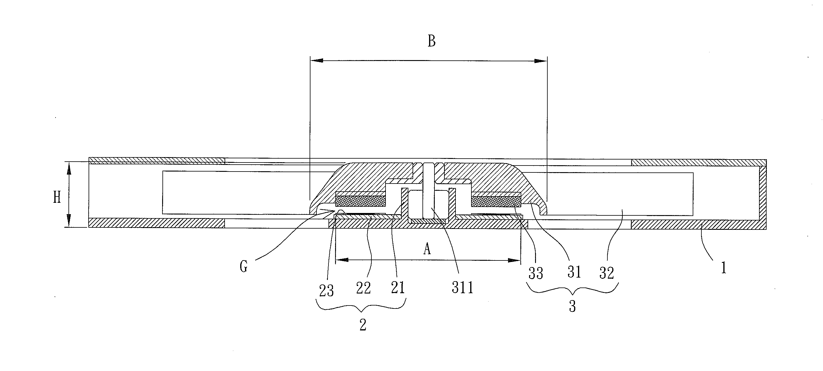
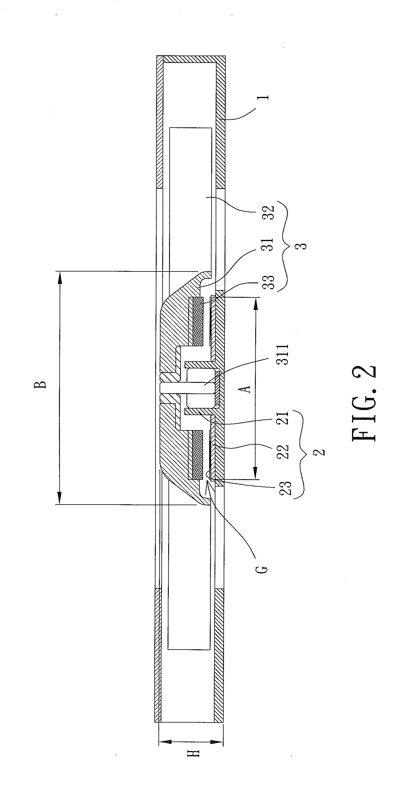
[0025]FIG. 2 shows a slim cooling fan having an axial air gap according to a first embodiment of the invention. The fan is comprised of a fan frame 1, a stator assembly 2 and an impeller 3. Stator assembly 2 is installed in fan frame 1. Impeller 3 is rotatably coupled with stator assembly 2 such that stator assembly 2 is able to drive impeller 3 to rotate. The fan may be an axial fan or a blower fan. In the embodiment, the fan is implemented as a blower fan, but is not limited thereto.

[0026]In FIG. 2, fan frame 1 is of any hollow frame where air is able to flow in and out of the frame. Stator assembly 2 includes a shaft-coupling portion 21, a base plate 22 and a coil unit 23. Shaft-coupling portion 21 may be integrally formed with fan frame 1. Alternatively, shaft-coupling portion 21 may also be affixed to or removed from fan frame 1. Base plate 22 is fitted around shaft-coupling portion 21 and is electrically connected to a driving circuit (not shown) which is used to drive impelle...


PUM


Abstract

A cooling fan having a motor is disclosed. The cooling fan includes a stator assembly and an impeller. The stator assembly includes a shaft-coupling portion and a coil unit. The impeller includes a hub and a magnetic element. An axial air gap is formed between the magnetic element and the coil unit. A height between a bottom face of the shaft-coupling portion and a top face of the hub is from 1.5 mm to 3.5 mm. The coil unit has a first maximum width, and the hub has a second maximum width. A ratio of the first maximum width to the second maximum width is from 0.7 to 1.3. A method for determining the dimensional proportion of the motor includes selecting a ratio of a first maximum width to a second maximum width as 0.7 to 1.3, and determining the values of the first and second maximum widths.

Description

BACKGROUND OF THE INVENTION[0001]1. Field of the Invention[0002]The present invention generally relates to a cooling fan and a method for determining the dimensional proportion of the motor of the cooling fan and, more particularly, to a slim cooling fan that has a reduced thickness and is equipped with an axial-air-gap motor, as well as a method for determining the dimensional proportion of the motor.[0003]2. Description of the Related Art[0004]In recent years, since the modern electronic products are miniaturized and have high performances, electronic elements inside the electronic product are liable to generate a large amount of heat during the operation of the electronic product. As a result, the heat of the electronic product cannot be expelled smoothly, especially in the small interior space of the electronic product. Disadvantageously, the performance of the electronic product is not stable or is even deteriorated, affecting the reliability of the electronic product. Thus, th...

Claims


Application Information

Patent Timeline
Patent Type & Authority Applications(United States)
IPC IPC(8): F04D25/06G01B21/02
CPCG01B21/02F04D25/0653F04D29/281
Inventor HORNG, ALEXWANG, TIAN-XUAN
Owner SUNONWEALTH ELECTRIC MACHINE IND
Why Eureka
Try Eureka