Method And Apparatus For Generating An Engineering Workflow

a workflow and engineering technology, applied in the field of engineering workflow generation methods and apparatus, can solve the problems of customer-specific and product-dependent, generated workflows can only be retracked to the original product core with difficulty, and conventional engineering tools do not provide systematic support for users or experts of the respective application domain

Inactive Publication Date: 2014-10-16
SIEMENS AG
View PDF55 Cites 10 Cited by
  • Summary
  • Abstract
  • Description
  • Claims
  • Application Information

AI Technical Summary

Benefits of technology

[0011]In a further possible embodiment of the computer system according to the first aspect of the present invention, each

Problems solved by technology

This naturally leads to customer-specific and product-dependent results.
Moreover, the generated workflows can only with difficulty and corresponding expert knowledge be retracked to the original product core.
Accordingly, conventional engineering

Method used


Image

  • Method And Apparatus For Generating An Engineering Workflow
  • Method And Apparatus For Generating An Engineering Workflow
  • Method And Apparatus For Generating An Engineering Workflow

Examples


Embodiment Construction

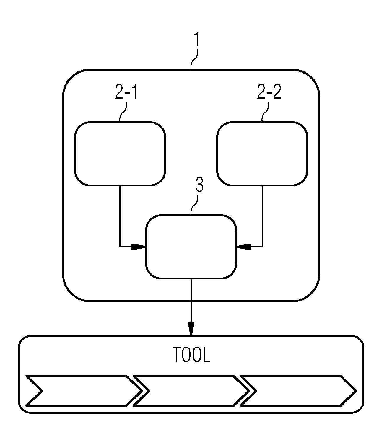
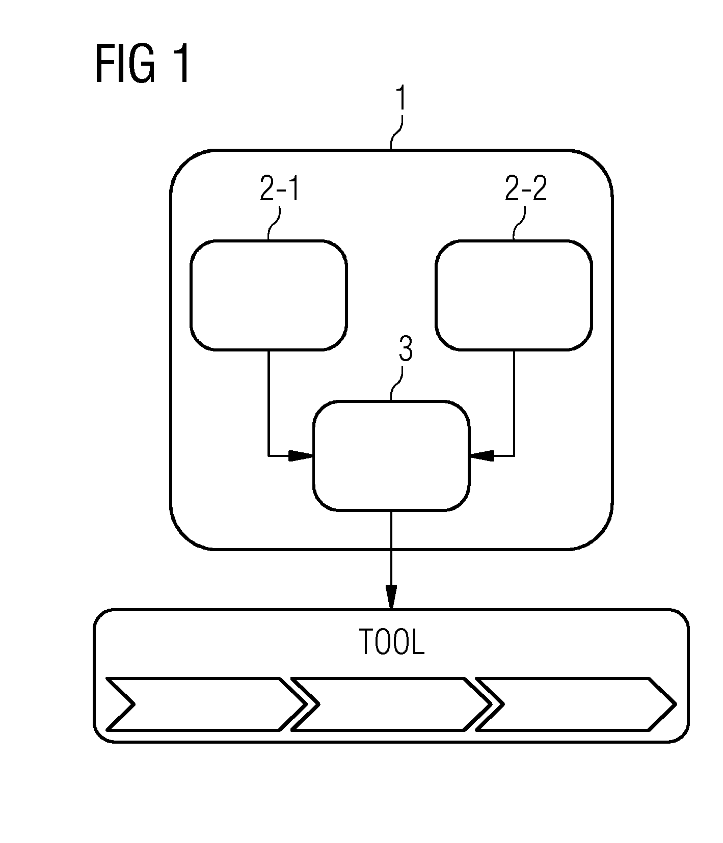
[0029]A first aspect of the present invention relates to a computer system which is configured to generate an engineering workflow. FIG. 1 shows a diagram for illustrating a possible embodiment of a computer system 1 according to the first aspect of the present invention which is configured to generate an engineering workflow or an engineering tool. The computer system 1 as illustrated in FIG. 1 comprises at least one calculation unit or processor which can have access to databases. As illustrated in FIG. 1, the computer system 1 comprises at least one first database 2-1 which stores a library of engineering patterns and a second database 2-2 which stores a library of engineering tool functions of an engineering tool. The computer system 1 further comprises a user interface 3 as illustrated in FIG. 1. The computer system 1 is configured to generate an engineering workflow wherein a sequence of automatically concatenated workflow steps forming said engineering workflow is generated b...


PUM


Abstract

Computer system configured to generate an engineering workflow, said system comprising a first database which stores a library of engineering patterns and a second database which stores a library of engineering tool functions of an engineering tool, wherein a sequence of automatically concatenated workflow steps forming said engineering workflow is generated by mapping for each workflow step a selected engineering pattern to a selected tool function of said engineering tool.

Description

CROSS-REFERENCE TO RELATED APPLICATIONS[0001]This application claims priority to EP Patent Application No. 13163264.8 filed Apr. 11, 2013. The contents of which is incorporated herein by reference in its entiretyTECHNICAL BACKGROUND[0002]Conventional engineering tools offer only a basic support of a workflow by providing tasks, documents or models in a defined sequence. The composition of a workflow is done manually. When customizing, these workflows are programmed by experts into the engineering tool by supplementing the source code of the engineering tool. This naturally leads to customer-specific and product-dependent results. Moreover, the generated workflows can only with difficulty and corresponding expert knowledge be retracked to the original product core.[0003]Accordingly, conventional engineering tools do not provide any systematic support for a user or an expert of the respective application domain of the engineering tool to compose or assemble his own individual workflow...

Claims


Application Information

Patent Timeline
IPC IPC(8): G06Q10/06
CPCG06Q10/06316
Inventor FOEHR, MATTHIASHORN, STEFANJAGER, TOBIASMUHLHAUSE, MATHIASSEIDEL, HEIKO
Owner SIEMENS AG
Why Eureka
Try Eureka