Design engineering tools for visualizing existing utility lines within a land area and validating placement of new utility lines

Inactive Publication Date: 2020-03-26
I D TECH INC
View PDF0 Cites 7 Cited by
  • Summary
  • Abstract
  • Description
  • Claims
  • Application Information

AI Technical Summary

Problems solved by technology

Thus, CAD drawings do not necessarily accurately reflect the reality of the utility lines as they actually exist in the field.
To date, there has been no mechanism that combines the two technologies together, namely, the ability to create and/or view CAD layers on a photo or on a map derived from the photo.
There also has been no such mechanism that could further identify conflicts between existing utility lines and a proposed utility line that an engineer wishes to implement.
These maps and drawings are not always accurate, however, because the cons

Method used


Image

  • Design engineering tools for visualizing existing utility lines within a land area and validating placement of new utility lines
  • Design engineering tools for visualizing existing utility lines within a land area and validating placement of new utility lines
  • Design engineering tools for visualizing existing utility lines within a land area and validating placement of new utility lines

Examples


Embodiment Construction

[0039]Design Tool

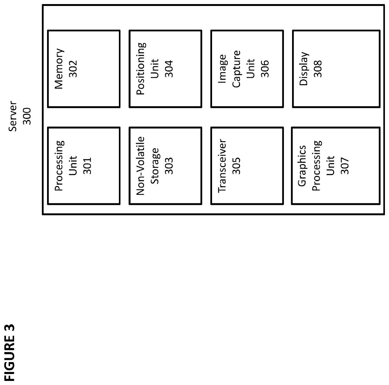
[0040]An embodiment of a computer-implemented design tool is depicted in FIGS. 1-5. The design tool is implemented using design system 500, which comprises client device 100 and server 300, as shown in FIG. 5. Applicant refers internally to this embodiment as “KAMEL.”

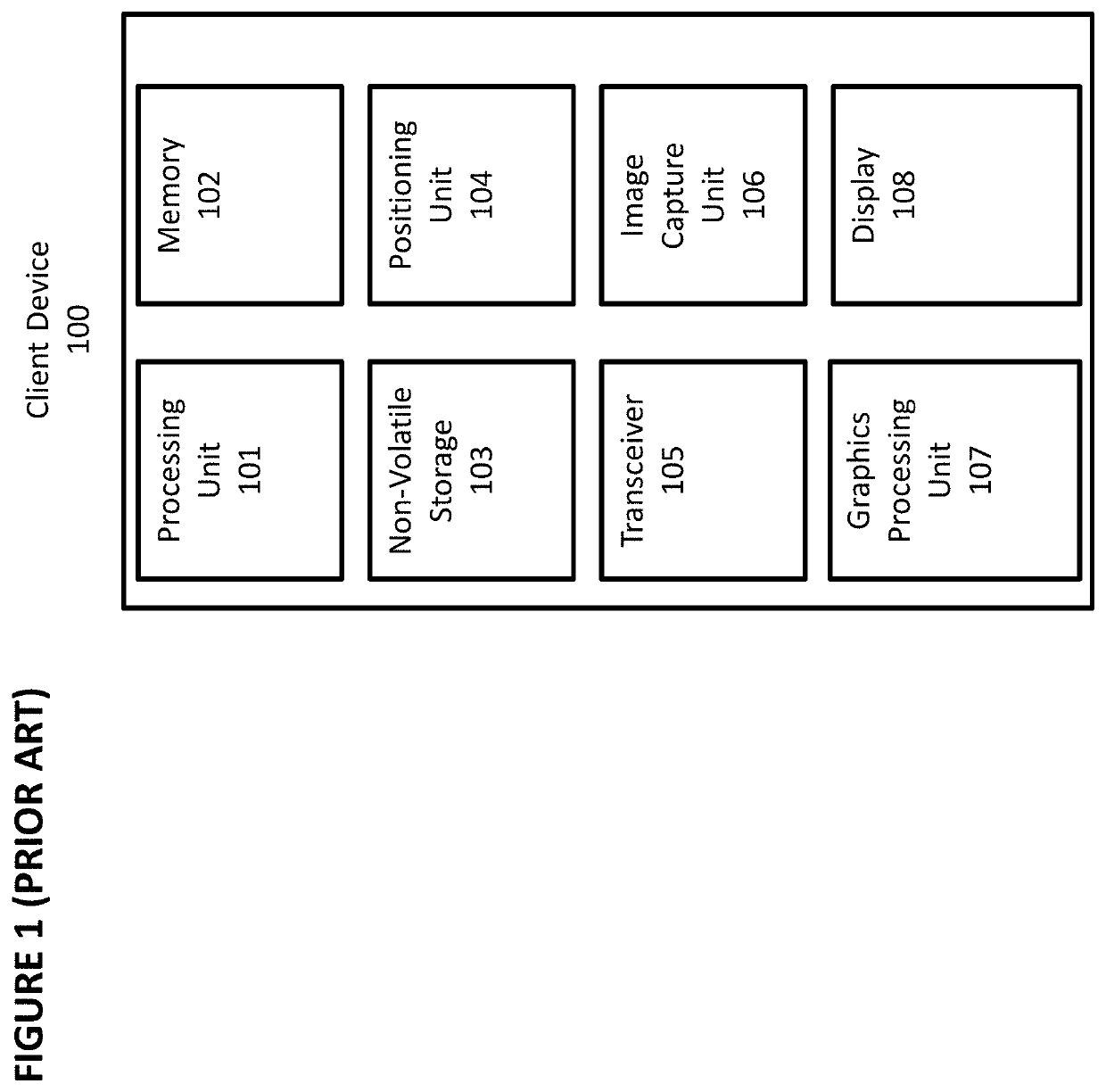
[0041]Client device 100 will first be described. FIG. 1 depicts hardware components of client device 100. These hardware components are known in the prior art. Client device 100 is a computing device that comprises processing unit 101, memory 102, non-volatile storage 103, positioning unit 104, network interface 105, image capture unit 106, graphics processing unit 107, and display 108. Client device 100 can be a smartphone, notebook computer, tablet, desktop computer, gaming unit, wearable computing device such as a watch or glasses, or any other computing device.

[0042]Processing unit 101 optionally comprises a microprocessor with one or more processing cores. Memory 102 optionally comprises DRAM or SR...


PUM


Abstract

A design engineering tool and associated method are disclosed. The design engineering tool and method allow a user to view a photo of a land area or a map derived from the photo, to overlay the photo or map with existing utility lines and proposed utility lines, and to generate alerts regarding any conflict that is identified between a proposed utility line and an existing utility line. The tool also has an augmented reality mode where it displays visualizations of existing and proposed utility lines over a real-time image obtained from a camera. Optionally, the exact location and condition of existing utility lines can be determined using radar and camera devices that generate data describing the location and physical characteristics of the utility lines. The generated data can be imported into the design engineering tool.

Description

PRIORITY CLAIM[0001]This application claims priority to U.S. Provisional Patent Application No. 62 / 737,013, filed on Sep. 26, 2018, and titled “Kamel Pre Engineering Visualization and New Pipe Route Validation and Mapping Tool”; U.S. Provisional Patent Application No. 62 / 737,027, filed on Sep. 26, 2018, and titled, “InfraEng Pre-Engineering Procedure”; U.S. Provisional Patent Application No. 62 / 738,484, filed on Sep. 28, 2018, and titled, “‘Archway’ Premises Construction, Maintenance / Repairs, and Emergency Response System Using Augmented Reality”; and U.S. Provisional Patent Application No. 62 / 737,031, filed on Sep. 26, 2018, and titled “GlobeSury Wireless Field Data Collector and Asset Management Tool,” all of which are incorporated by reference herein.FIELD OF THE INVENTION[0002]A design engineering tool and associated method are disclosed. The design engineering tool and method allow a user to view a photo of a land area or a map derived from the photo, to overlay the photo or ma...

Claims


Application Information

Patent Timeline
IPC IPC(8): G06F17/50G06K9/00G01C11/04
CPCG01S13/885G01C11/04G06K9/00671G06F30/00G06F30/18G09B29/007G06Q10/20G06Q50/06G06F30/13G06T19/006G06V20/20
Inventor AGOURIDIS, DIMITRIS
Owner I D TECH INC
Why Eureka
Try Eureka