Fuel nozzle for a pre-mix combustor of a gas turbine engine

a technology of fuel nozzle and combustor, which is applied in the direction of machines/engines, combustion types, lighting and heating apparatus, etc., can solve the problems of adversely affecting the mechanical life of the fuel nozzle, the swirler and/or the combustor, and the higher the rate of nox emission

Active Publication Date: 2014-10-23
GENERAL ELECTRIC CO
View PDF17 Cites 15 Cited by
  • Summary
  • Abstract
  • Description
  • Claims
  • Application Information

AI Technical Summary

Problems solved by technology

The higher the temperature of the combustion gases, the higher the rate of formation of the undesirable NOx emissions.
Flashback typically occurs when flame propagates upstream from the combustion chamber into the pre-mix chamber, typically caused by momentary transient conditions.
Flashback and / or flame holding conditions within the combustor may result in undesirable thermal stresses on the fuel nozzles, thereby adversely affecting the mechanical life of the fuel nozzles, the swirlers and / or the combustor.

Method used


Image

  • Fuel nozzle for a pre-mix combustor of a gas turbine engine
  • Fuel nozzle for a pre-mix combustor of a gas turbine engine
  • Fuel nozzle for a pre-mix combustor of a gas turbine engine

Examples


Embodiment Construction

[0020]Reference will now be made in detail to present embodiments of the invention, one or more examples of which are illustrated in the accompanying drawings. The detailed description uses numerical and letter designations to refer to features in the drawings. Like or similar designations in the drawings and description have been used to refer to like or similar parts of the invention.

[0021]As used herein, the terms “first”, “second”, and “third” may be used interchangeably to distinguish one component from another and are not intended to signify location or importance of the individual components. The terms “upstream,”“downstream,”“radially,” and “axially” refer to the relative direction with respect to fluid flow in a fluid pathway. For example, “upstream” refers to the direction from which the fluid flows, and “downstream” refers to the direction to which the fluid flows. Similarly, “radially” refers to the relative direction substantially perpendicular to the fluid flow, and “a...


PUM


Abstract

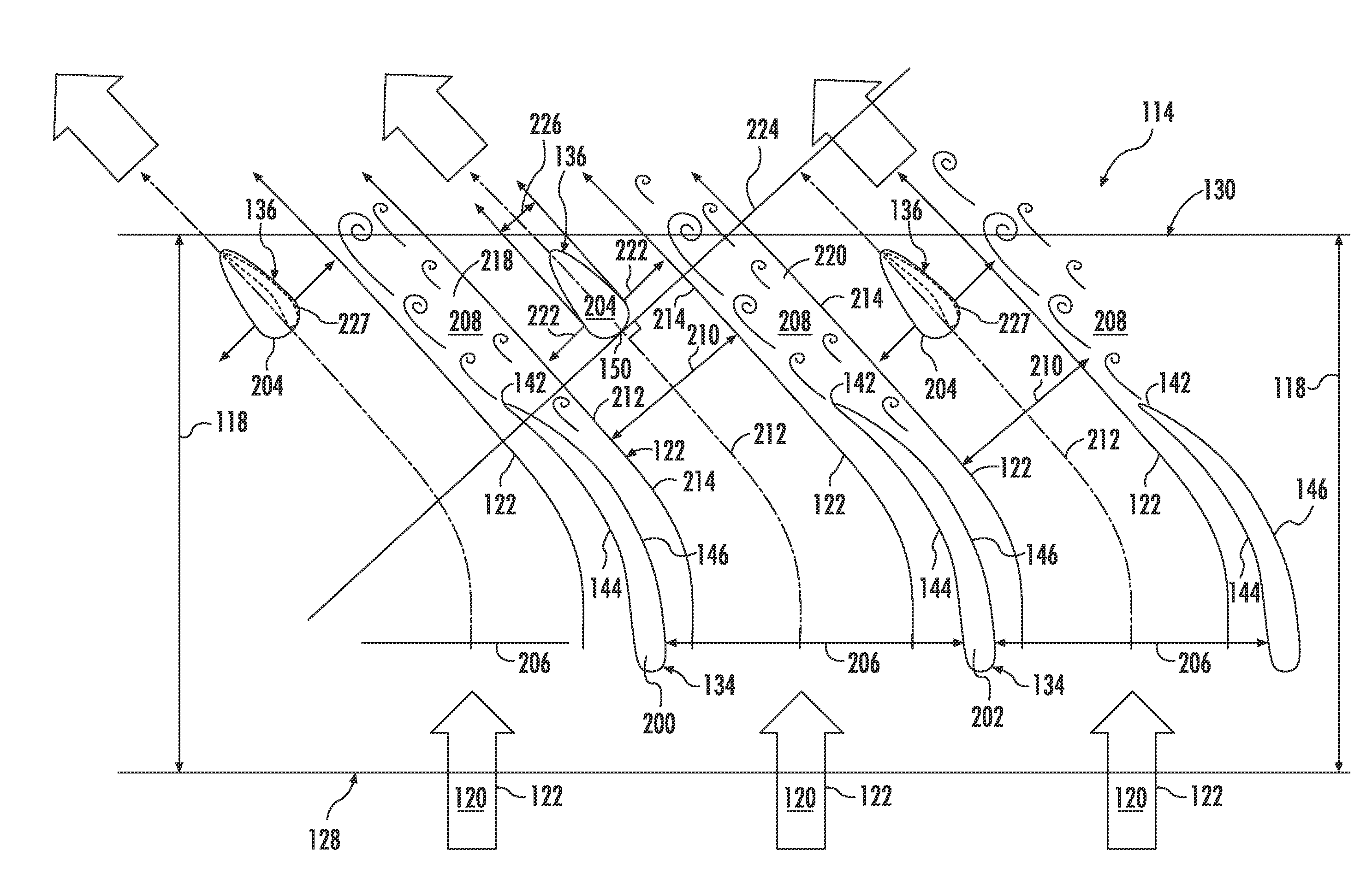
A fuel nozzle for use in a gas turbine includes a pre-mix flow passage for directing a flow segment of a flow of a working fluid through the fuel nozzle. A first swirler vane and a second swirler vane extend within the pre-mix flow passage. The first swirler vane provides a first wake region within the flow segment. The second swirler vane provides a second wake region within the flow segment. A fuel injection peg is disposed downstream from the first swirler vane and the second swirler vane. The fuel injection peg is positioned within the flow segment between the first wake region and the second wake region.

Description

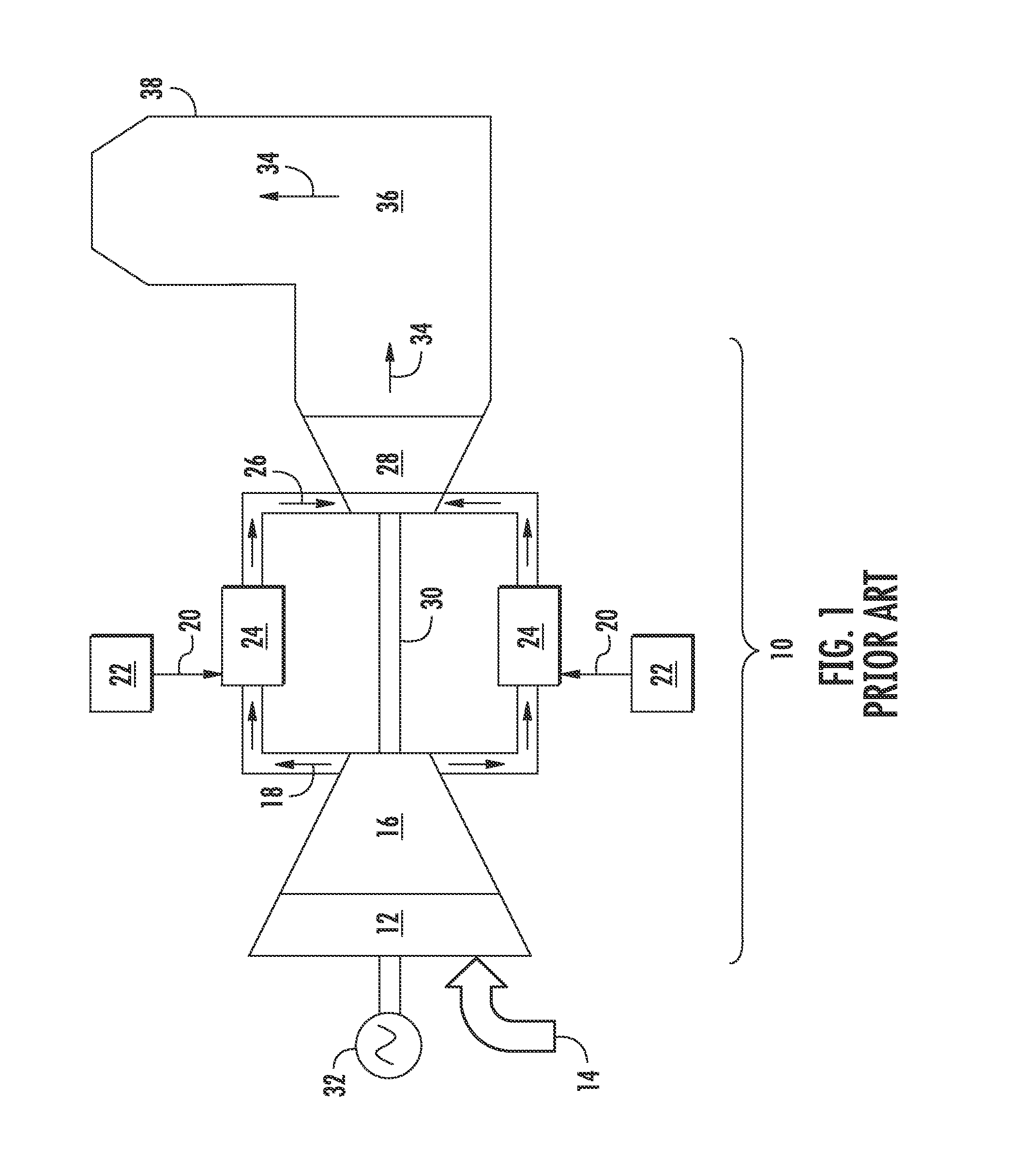
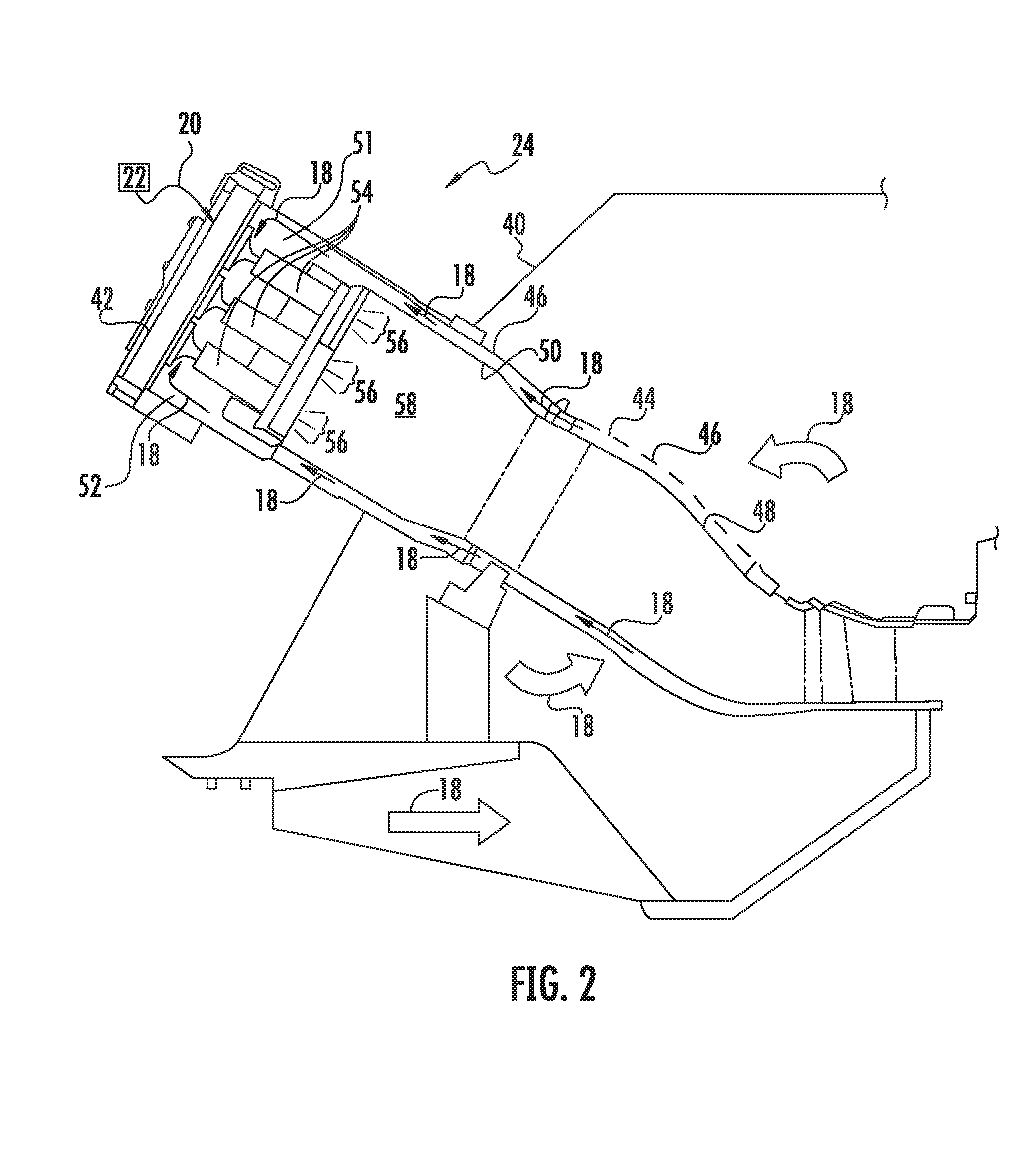
FIELD OF THE INVENTION[0001]The present invention generally relates to a fuel nozzle for use in a pre-mix combustor of a gas turbine. More particularly, this invention relates to a fuel nozzle having a pre-mix flow passage.BACKGROUND OF THE INVENTION[0002]A typical gas turbine includes an inlet section, a compressor section, a combustion section, a turbine section, and an exhaust section. The inlet section cleans and conditions a working fluid (e.g., air) and supplies the working fluid to the compressor section. The compressor section progressively increases the pressure of the working fluid and supplies a compressed working fluid to the combustion section. The compressed working fluid and a fuel are mixed within the combustion section and burned in a combustion chamber to generate combustion gases having a high temperature and pressure. The combustion gases are routed along through a hot gas path into the turbine section where they expand to produce work. For example, expansion of ...

Claims


Application Information

Patent Timeline
Patent Type & Authority Applications(United States)
IPC IPC(8): F23R3/28F23R3/14
CPCF23R3/14F23R3/286F23D14/24F23D2900/14004F23D2900/14021F23R3/32
Inventor PINSON, MARK WILLIAMJENSEN, GREGORY EARLTERRY, JASON CHARLES
Owner GENERAL ELECTRIC CO
Why Eureka
Try Eureka