Image Processing System for a Vehicle

Active Publication Date: 2014-10-23
BAYERISCHE MOTOREN WERKE AG
View PDF1 Cites 8 Cited by
  • Summary
  • Abstract
  • Description
  • Claims
  • Application Information

AI Technical Summary

Benefits of technology

[0011]In a further advantageous embodiment, the overall video signal is ascertained in such a way that a weighting of an overlay of the respective pixels of the first video image and of the second video image is carried out as a function of the fourth pixel values of the first video image representing the transparency. Advantageously, this allows the respective first video image to be inserted into the respective second video image in such a way that no transitions between the respective first video image and the respective second video image are visible to an observer of the respective image-in-image video images when the image-in-image video images are displayed by way of an output device. Moreover, this makes it impossible for an observer to detect which unit provides which image contents in the respective image-in-image video image.
[0012]In a further advantageous embodiment, the first unit is designed to generate the first video image signal. This enables a compact design of the image processing system.
[0013]In a further advantageous embodiment, the second unit is designed to generate the second video image signal. Advantageously, this also enables a compact design of the image processing system.
[0014]In a further advantageous embodiment, the first unit is designed to convert the respective first video image signal into the transformed video image signal in such a way that the transformed video image signal represents a transformed video image, which has the same pixel values as the first video image and a number of pixels greater by a factor of 4/3 than the first video image and in which in each case three pixel values are assigned to the respective pixels of the transformed video image. Advantag

Problems solved by technology

However, due to the multitude of visual output devices, which are increasingly designed as displays, it is difficult for a vehicle user and/or vehicle driver to reliably gather the most important information from a nu

Method used


Image

  • Image Processing System for a Vehicle
  • Image Processing System for a Vehicle
  • Image Processing System for a Vehicle

Examples


Example

DETAILED DESCRIPTION OF THE DRAWINGS

[0023]Elements that are identical in terms of design or function are denoted by identical reference numerals throughout the figures.

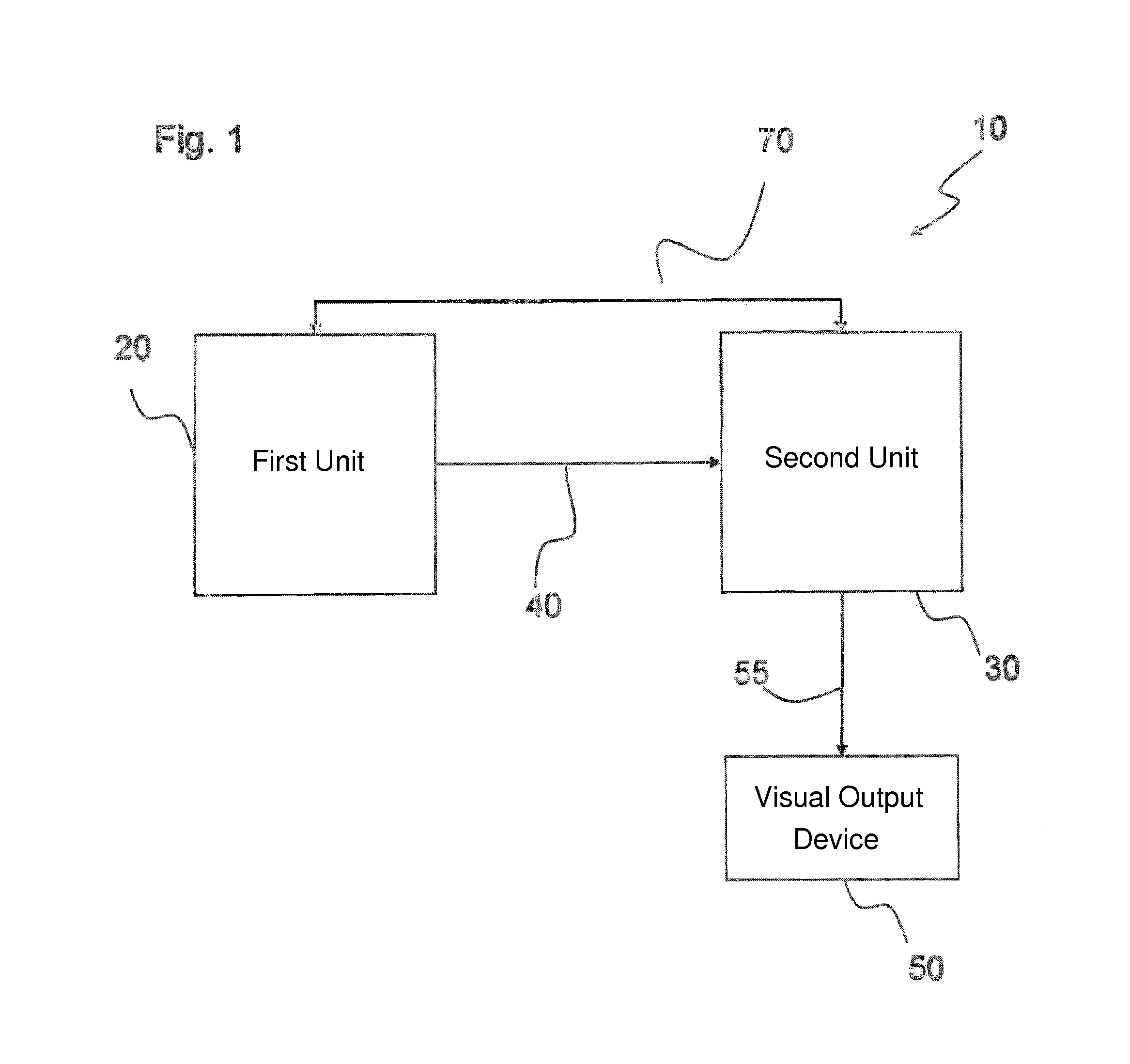
[0024]FIG. 1 shows an image processing system 10 for a vehicle. The vehicle can be designed as a motor vehicle, for example. The image processing system 10 comprises a first unit 20, a second unit 30 and a video transmission link 40.

[0025]The video transmission link 40 couples the first unit 20 and the second unit 30 in terms of signaling for transmitting digital video data.

[0026]For example, the video transmission link 40 can include an Automotive Pixel Link (APIX). The APIX is designed in such a way that it meets special requirements in the vehicle environment; for example, the APIX has an increased temperature range and / or higher immunity to interference and / or lower electromagnetic emission compared to video transmission links used in private households.

[0027]Such an APIX thus allows reliable and cost-effective vi...


PUM


Abstract

An image processing system for a vehicle includes a first unit, a second unit and a video transmission link, which couples the first and second units, in terms of signaling, for transmitting digital video data. The video transmission link transmits digital video image signals having a predefined data format for a respective pixel of a video image, the data format including three blocks, each having a predefined number of bits. The first unit ascertains an uncompressed transformed video image signal suitable for transmission via the video transmission link as a function of a respective first video image signal such that the transformed video image signal has the predefined data format of the video transmission link. The first video image signal represents respective uncompressed first video images of a sequence of first video images, which are provided at a predefined frame rate and which, in each case, have a first image resolution having a predefined number of pixels, wherein in each case four pixel values are assigned to the respective pixels of the first video image. The second unit is designed to again ascertain the first video image signal as a function of the transformed video image signal received via the transmission link.

Description

CROSS REFERENCE TO RELATED APPLICATIONS[0001]This application is a continuation of PCT International Application No. PCT / EP2012 / 075526, filed Dec. 14, 2012, which claims priority under 35 U.S.C. §119 from German Patent Application No. 10 2012 200 264.2, filed Jan. 10, 2012, the entire disclosures of which are herein expressly incorporated by reference.BACKGROUND AND SUMMARY OF THE INVENTION[0002]The invention relates to an image processing system for a vehicle, including a first unit, a second unit and a video transmission link, which couples the first unit and the second unit in terms of signaling for transmitting digital video data.[0003]In a vehicle, such as in a motor vehicle, an increasing amount of information is provided to the vehicle user and / or vehicle driver by way of visual output devices. However, due to the multitude of visual output devices, which are increasingly designed as displays, it is difficult for a vehicle user and / or vehicle driver to reliably gather the mos...

Claims


Application Information

Patent Timeline
IPC IPC(8): H04N7/24H04N21/4402H04N7/01
CPCH04N7/24B60R2300/30H04N21/440218H04N7/01G09G5/026H04N7/108H04N9/76H04N21/41422G09G2380/10H04L12/6418G09G5/397G09G2340/06G09G2340/12G09G2370/02G09G5/006G09G2370/12
Inventor SCHRAMM, ANDREASBAUR, THILO
Owner BAYERISCHE MOTOREN WERKE AG
Why Eureka
Try Eureka