
Floor Element, Locking System for Floor Elements, Floor Covering and Method for Composing Such Floor Elements to a Floor Covering

a technology of locking system and floor element, which is applied in the field of floor element, locking system of floor element, floor covering and method for composing such floor elements to a floor covering, can solve the problems of less installation cost of such floor covering, more expensive than a floor covering, and difficulty in installing such floor elements, so as to achieve increased laying or installation comfort

Active Publication Date: 2014-10-30
FLOORING IND LTD
View PDF4 Cites 19 Cited by
  • Summary
  • Abstract
  • Description
  • Claims
  • Application Information

AI Technical Summary

Benefits of technology

[0015]The particularity of the first aspect of the present invention is situated in the fact that at least two components of a floor element form an entity and still can adopt positions differing in respect to each other. In this way, it is possible to design a floor element, said entity thereof allowing the user to adapt the shape of the floor element, for example, when installing the floor element. Further, it is possible that said components of the floor elements adopt a certain mutual position in the package, for example, a mutual position in which the floor elements can easily be packaged, whereas the user still can readjust or adjust this position before or during the installation of the floor covering. Preferably, said components may adopt a mutual position in which the floor element has a globally rectangular shape. A rectangular or square shape is very beneficial for packaging the floor elements.
[0066]In a preferred embodiment of the fifth aspect, said elastic deformation and / or the bending of the respective lip decreases during the first and / or the second change, until it is approximately completely or completely relaxed. When at the end of the first change a complete relaxation is obtained, the comfort of shifting both floor elements or components along the coupled sides is maximized.

Problems solved by technology

In connection with the shorter installation time, also the installation cost of such floor covering is lower.
However, the fact that smaller floor elements or floor elements with smaller, in particular less wide, decorative parts, in particular when wood parquets or parquet imitations are concerned, are much desired from an esthetically point of view, is contradictory to the aforementioned striving.
It is also noted that, although smaller wooden floor elements in respect to material costs per unit of surface area are cheaper than large wooden floor elements, the higher installation costs for smaller floor elements result in that, when the total cost price of the floor covering is brought into account, they will be more expensive than a floor covering composed of large wooden floor elements.
Moreover, long, narrow floor elements show the tendency to warp around an axis perpendicular to their decorative side, which leads to problems when installing such floor elements.
These problems are very pronounced when the floor elements are installed without glue, i.e., for example, by means of mechanical coupling means, as the aforementioned warping results in difficulties when engaging the coupling means.
The herein above-described rectangular floor elements originating from the state of the art have the disadvantage that it is impossible to compose, starting therefrom, a floor covering with a random bond of decorative parts, as the decorative parts of each time two or more adjacent rows, depending whether a two-plank or a multi-plank, respectively, are concerned, in longitudinal direction of the rows concerned necessarily simultaneously merge into decorative parts of another floor element in the floor covering.
The lack of a random bond in such floor covering is seen as disturbing.
It is evident that this technique can only be applied to floor elements with artificially obtained decorative portions, such as decorative portions comprising a printed decor.
Moreover, the adaptation of the printed decor in order to obtain such matching is time-consuming and represents a huge restriction of the freedom of design.
Also, the lack of a random bond still will be noticeable when, for example, minimal height differences between the different floor elements are present.
First, the bond which can be obtained by means of such floor elements, still can not relate to a real random bond, as in each case the same step shape would be recognizable in the floor covering, and second, the suggested floor elements, due to their stepped shape, are difficult to package.

Method used


Image

  • Floor Element, Locking System for Floor Elements, Floor Covering and Method for Composing Such Floor Elements to a Floor Covering
  • Floor Element, Locking System for Floor Elements, Floor Covering and Method for Composing Such Floor Elements to a Floor Covering
  • Floor Element, Locking System for Floor Elements, Floor Covering and Method for Composing Such Floor Elements to a Floor Covering

Examples


Embodiment Construction

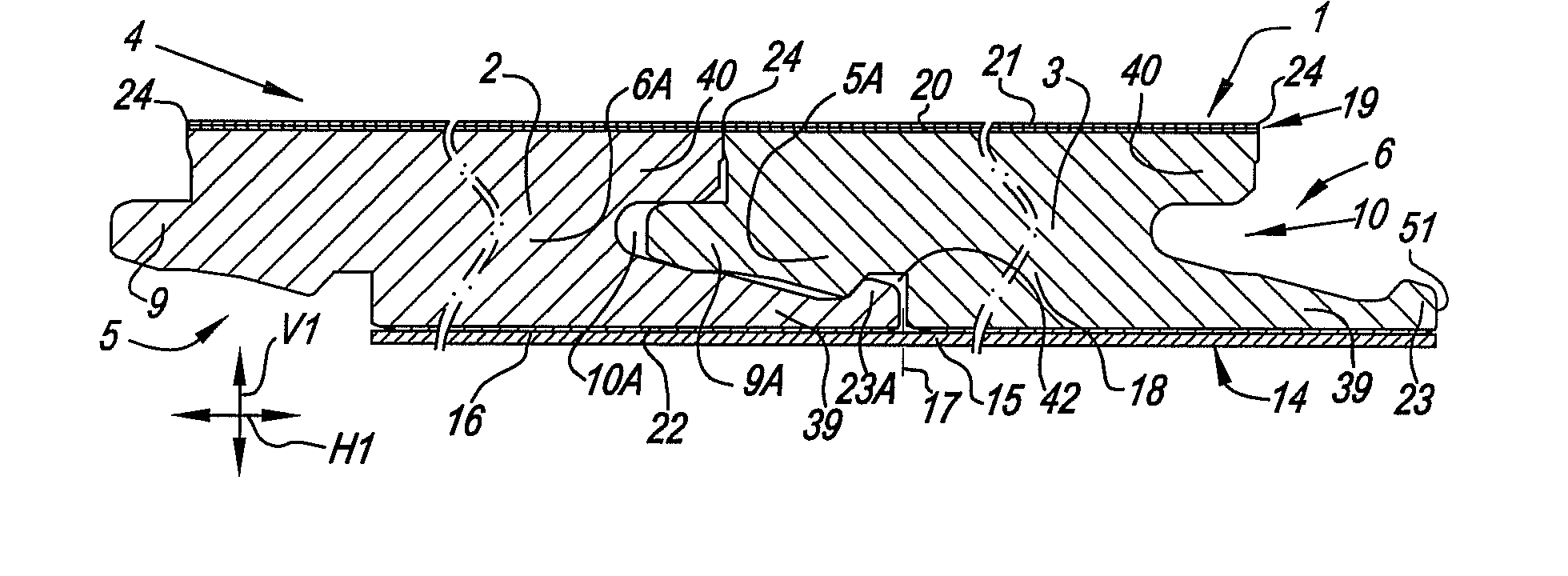
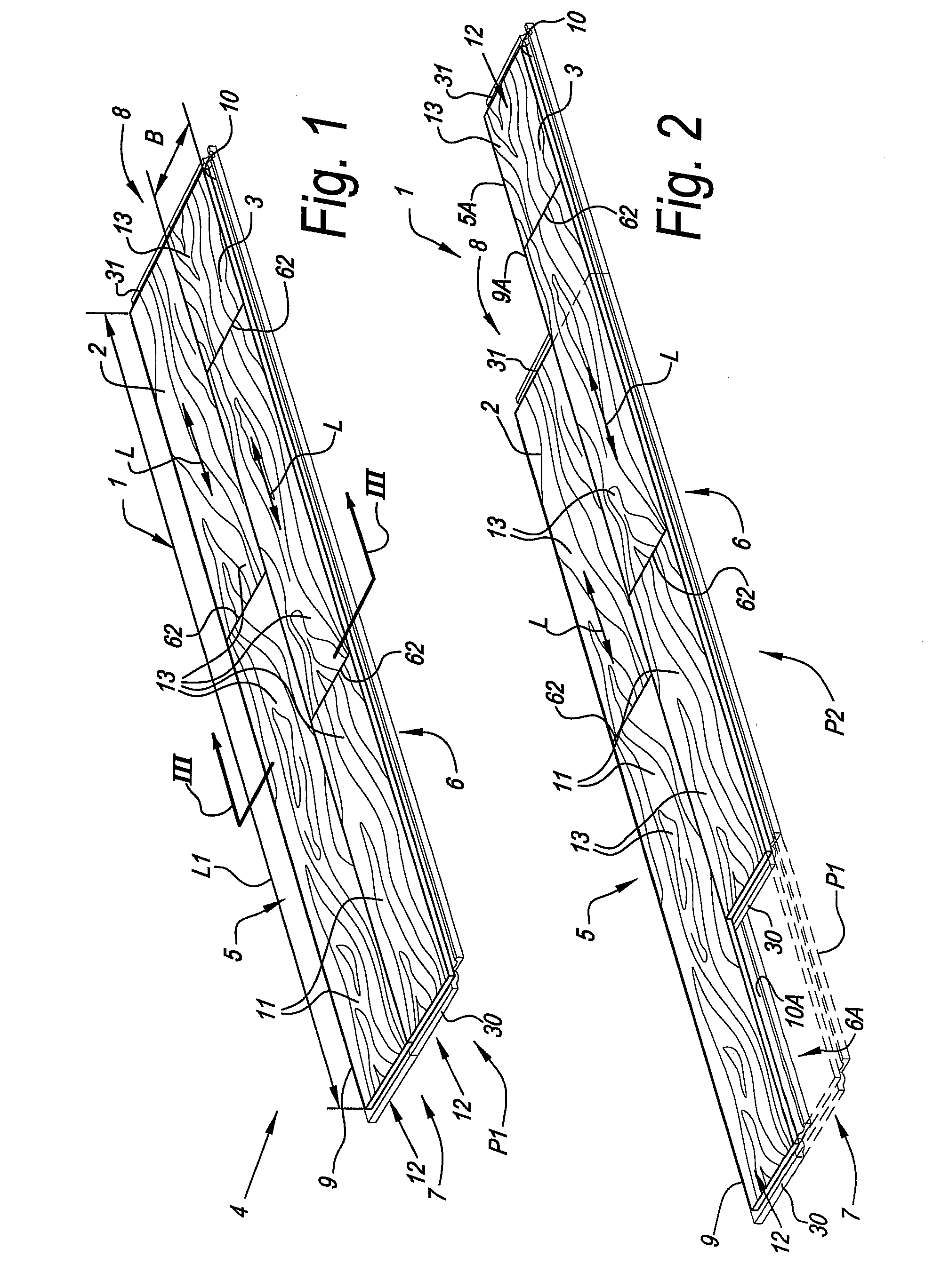
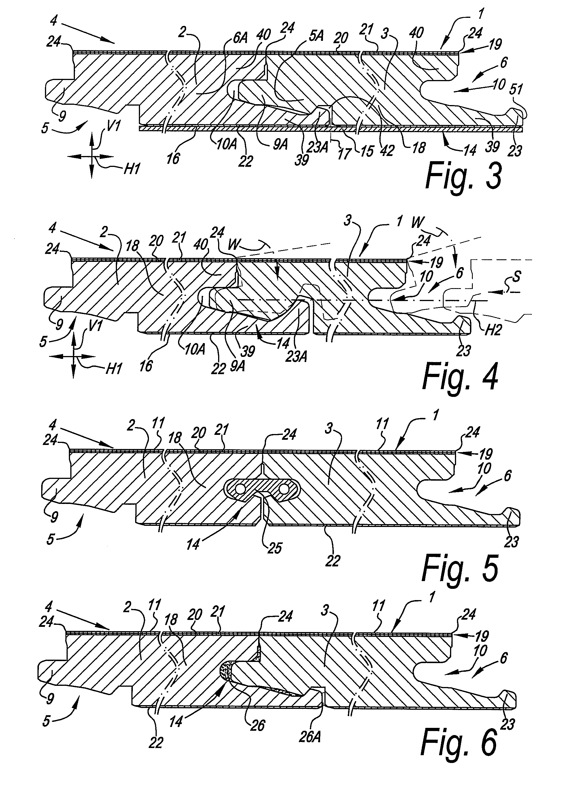
[0096]FIG. 1 represents a floor element 1 according to the invention. Such floor element 1, as aforementioned, is composed, as aforementioned, starting from at least two components 2-3, into an entity 4. In the example, the floor element comprises two components which are realized as planks or laths, which, as FIG. 1 shows, can adopt a mutual position P1 in which the floor element 1 has a globally rectangular and in this case oblong shape. In this mutual position P1, it is clear that the depicted floor element 1 has, at least at two opposite edges 5-6, for example, at the opposite long edges 5-6 and / or short edges 7-8, coupling means or coupling parts 9-10. In this case, the coupling means substantially are made in the form of a tongue 9 and a groove 10 and allow for that two of such floor elements 1 can be coupled to each other at the respective edges 5-6-7-8.

[0097]Each of said components 2-3 has a substantially flat side forming a decorative side 11. These decorative sides 11 are ...


PUM

PropertyMeasurementUnit
angleaaaaaaaaaa
widthaaaaaaaaaa
widthaaaaaaaaaa

Abstract

Floor element of the type which, at least at two opposite edges, comprises coupling means enabling two of such floor elements to cooperate with each other at the respective edges, wherein the floor element comprises at least two components, as well as entity-forming means, which, starting from the aforementioned components, can form an entity including the components, wherein said components can adopt at least two mutual positions, whether or not by means of the disruption of the entity formed by said entity-forming means.

Description

BACKGROUND OF THE INVENTION[0001]1. Field of the Invention[0002]This invention relates to floor elements, as well as to floor coverings which are composed of such floor elements, and to a method for composing such floor elements to a floor covering. The invention also relates to locking systems which can be applied in the aforementioned floor elements.[0003]2. Related Art[0004]More particularly, the invention relates to floor elements, which are intended for forming a floating floor covering and which, during installation, can be coupled at their edges by means of mechanical coupling parts, the latter either being made in one piece with the floor element or not. Such coupling parts can be made such that they provide for a mutual locking of the floor elements in horizontal as well as in vertical direction, for example, as described in the international patent applications WO 94 / 26999, WO 97 / 47834, WO 01 / 98603 and WO 01 / 96688.[0005]In order to increase the installation comfort of such...

Claims


Application Information

Patent Timeline
Patent Type & Authority Applications(United States)
IPC IPC(8): E04F15/02
CPCE04F15/02038E04F15/02033E04F15/04E04F15/048E04F2201/0115E04F2201/0138E04F2201/0153E04F2201/05E04F2201/0523E04F15/041E04F15/02194E04F15/042E04F15/082E04F15/085E04F15/087E04F15/102E04F15/105E04F15/107E04F15/043E04F2201/0123Y10T428/167E04F15/022E04F15/02E04F2201/0107E04F2201/023
Inventor SCHACHT, BENNYVANHASTEL, LUCCAPPELLE, MARK
Owner FLOORING IND LTD
Learn More