Thermal module

Active Publication Date: 2014-10-30
ASIA VITAL COMPONENTS SHENZHEN CO LTD
View PDF26 Cites 1 Cited by
  • Summary
  • Abstract
  • Description
  • Claims
  • Application Information

AI Technical Summary

Benefits of technology

The present invention provides a thermal module with higher heat dissipation efficiency. The module has a large-area heat transfer effect and a remote end heat transfer effect. A third capillary structure is placed on the outer surface of the conduction section to significantly improve the overall heat transfer efficiency of the module.

Problems solved by technology

The heat generated by the miniaturized components of the electronic apparatus has become a major obstacle to having better performance of the electronic apparatus and system.
The challenge to cooling the product due to increase of thermal flux exceeds the challenge simply caused by increase of total heat.
This is because the increase of thermal flux will lead to overheating at different times with respect to different sizes and may cause malfunction or even burnout of the electronic apparatus.
However, the vapor chamber has a critical shortcoming that it can hardly transfer the heat to a remote end to dissipate the heat.
Therefore, the heat transfer effect is limited.

Method used


Image

  • Thermal module
  • Thermal module
  • Thermal module

Examples


Embodiment Construction

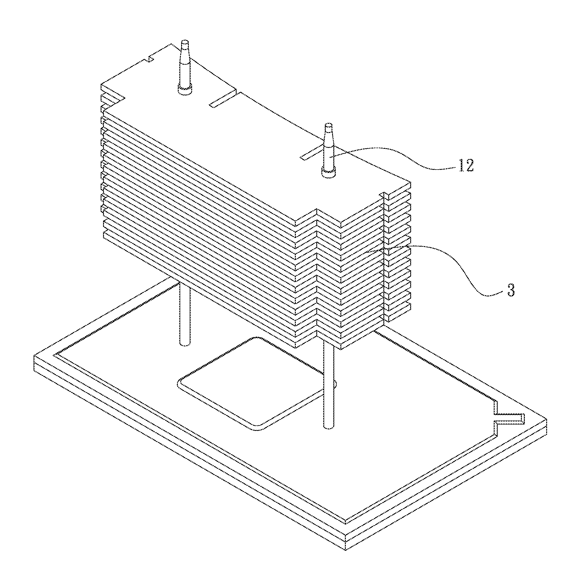
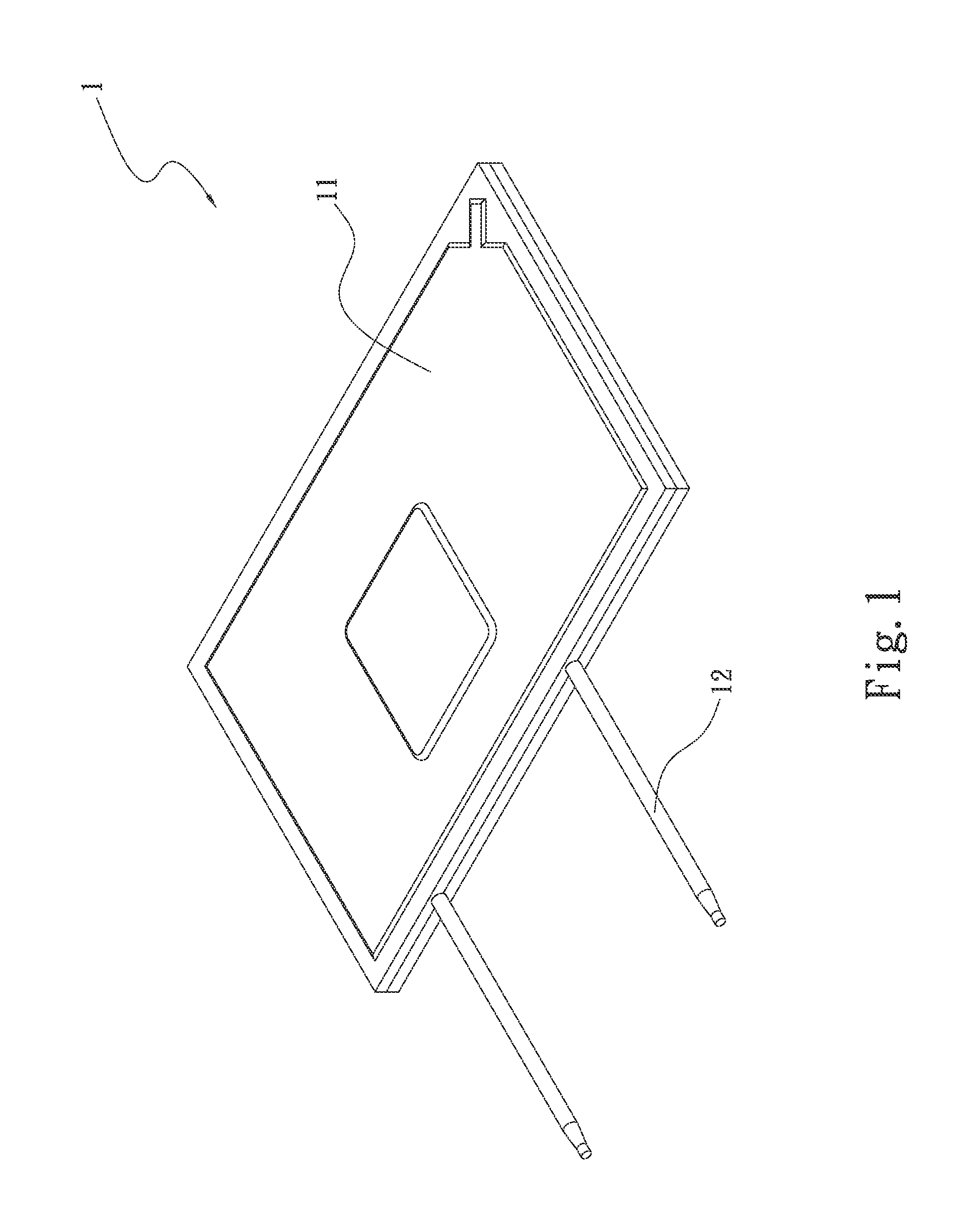
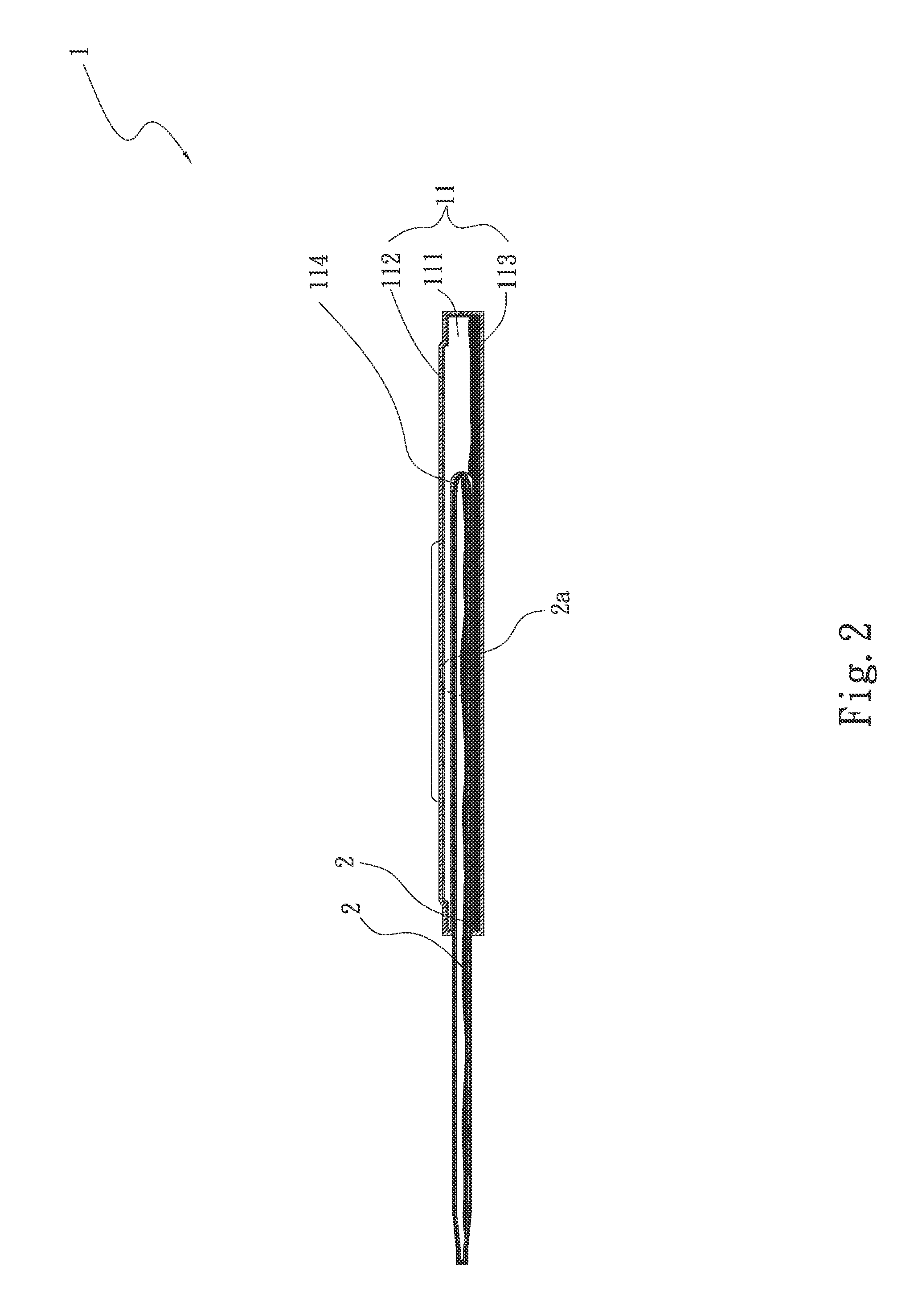
[0022]Please refer to FIGS. 1, 2 and 2a. FIG. 1 is a perspective view of a first embodiment of the thermal module of the present invention. FIG. 2 is a sectional assembled view of the first embodiment of the thermal module of the present invention. FIG. 2a is an enlarged view of circled area of FIG. 2. According to the first embodiment, the thermal module 1 of the present invention includes a first heat transfer member 11 and a second heat transfer member 12.

[0023]The first heat transfer member 11 has a first chamber 111 in which a first capillary structure 112 is disposed. The second heat transfer member 12 has a second chamber 121 and a conduction section 122. A second capillary structure 123 is disposed in the second chamber 121. The conduction section 122 is received in the first chamber 111. A third capillary structure 114 is disposed on outer surface of the conduction section 122. A working fluid 2 is respectively filled in the first and second chambers 111, 112.

[0024]The firs...


PUM


Abstract

A thermal module includes a first heat transfer member and a second heat transfer member. The first heat transfer member has a first chamber in which a first capillary structure is disposed. The second heat transfer member has a second chamber and a conduction section. A second capillary structure is disposed in the second chamber. The conduction section is received in the first chamber. A third capillary structure is disposed on outer surface of the conduction section. A working fluid is respectively filled in the first and second chambers. The third capillary structure is disposed on the outer surface of the conduction section to enhance the heat transfer effect of the second heat transfer member so as to enhance the heat transfer efficiency of the entire thermal module.

Description

BACKGROUND OF THE INVENTION[0001]1. Field of the Invention[0002]The present invention relates generally to a thermal module, and more particularly to a thermal module having both a large-area heat transfer effect and a remote end heat transfer effect.[0003]2. Description of the Related Art[0004]There is a trend to develop thinner and thinner electronic apparatuses nowadays. The ultra-thin electronic apparatus includes miniaturized components. The heat generated by the miniaturized components of the electronic apparatus has become a major obstacle to having better performance of the electronic apparatus and system. Even if the semiconductors forming the electronic component have been more and more miniaturized, the electronic apparatus is still required to have high performance.[0005]The miniaturization of the semiconductors will lead to increase of thermal flux. The challenge to cooling the product due to increase of thermal flux exceeds the challenge simply caused by increase of to...

Claims


Application Information

Patent Timeline
IPC IPC(8): F28D15/04F28F3/08
CPCF28F3/08F28D15/046F28D15/0275F28F1/32H01L23/3672H01L23/427H01L23/467H01L2924/0002
Inventor YANG, HSIU-WEI
Owner ASIA VITAL COMPONENTS SHENZHEN CO LTD
Why Eureka
Try Eureka